This helps you quickly interpret patents by identifying the three key elements:
Problems solved by technology
Method used
Benefits of technology
Benefits of technology
[0007]The present invention provides a liquid processing apparatus which can prevent a cleaning solution from remaining on a lifter of a target object. Thus, the liquid processing apparatus according to the present invention can prevent an attachment of a cleaning solution to an opposite surface of a target object, and prevent an inflow of the cleaning solution into an inert gas supply part to efficiently supply the inert gas to the target object.
[0009]Accordingly, the cleaning solution can be prevented from remaining on the lift pin plate, and also prevented from being attached to an opposite surface of the object. Further, the cleaning solution can be prevented from flowing into the inert gas supply part, and the inert gas can be efficiently supplied to the object.
[0016]Accordingly, the cleaning solution can be prevented from remaining on the lift pins of the lift pin plate.
[0018]Accordingly, the cleaning solution can be efficiently shaken off by rotating the support plate, and air fluctuation can be prevented.
Problems solved by technology
If the cleaning solution is attached to the wafer as described above, not only watermarks may be formed on the wafer to which the droplet is attached, but also the humidity in a carrier for conveying the wafer may be increased, thereby causing the formation of watermarks on other wafers accommodated in the carrier.
Method used
Image
Click on the blue label to locate the original text in one second.
Reading with bidirectional positioning of images and text.
Examples
first example
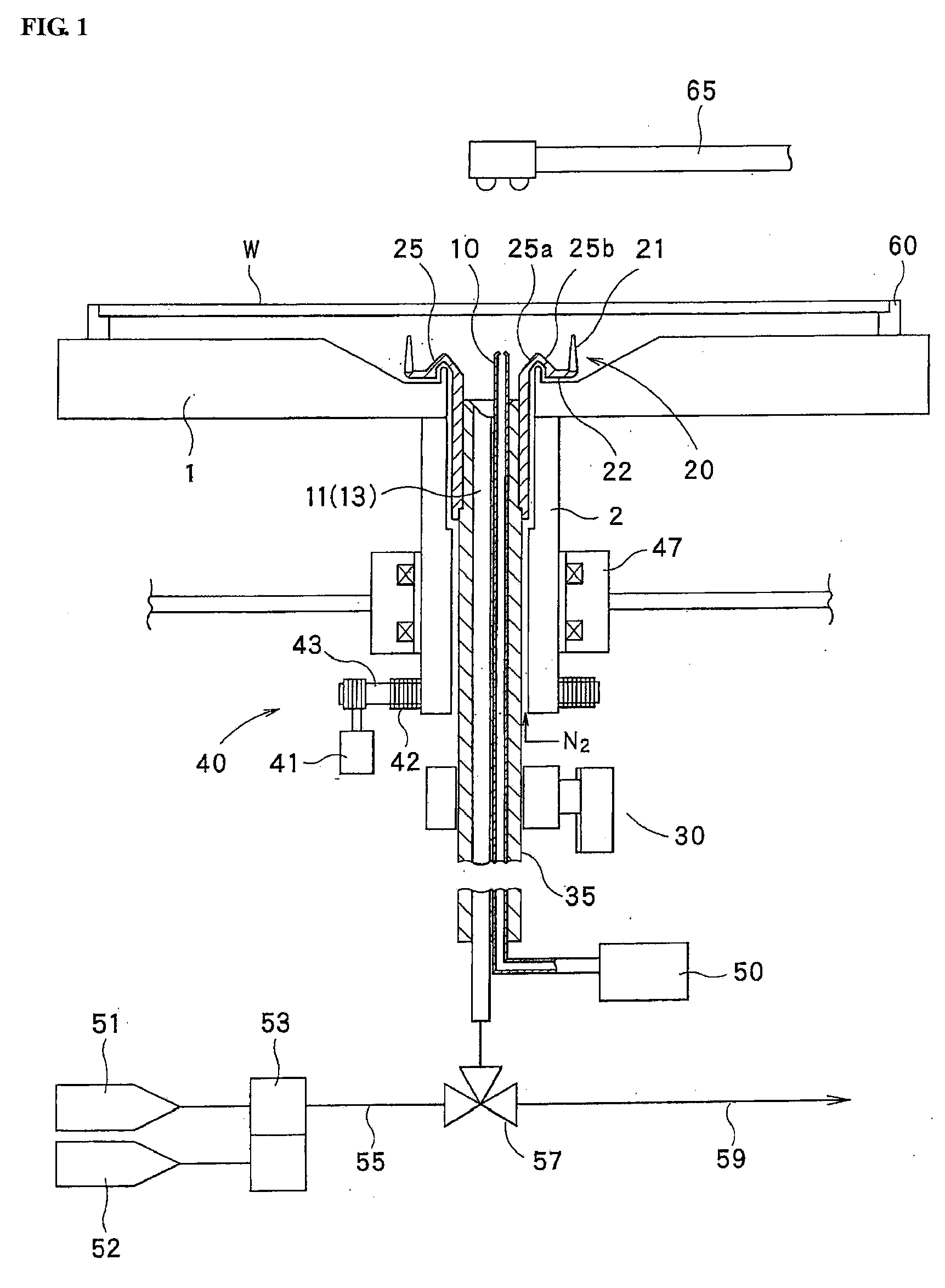
[0032]Hereinafter, a liquid processing apparatus and method according to a first example of the present invention will be described with reference to the accompanying drawings. FIGS. 1, 2, 3 and 5 are views each illustrating the liquid processing apparatus according to the first example, and FIG. 4 is a flowchart illustrating the liquid processing method according to the first example.
[0033]As illustrated in FIG. 1, the liquid processing apparatus includes a hollow-shaped support plate 1, a hollow-shaped rotary shaft 2 fixedly connected to the hollow-shaped support plate 1, and a rotary drive part 40 rotating the rotary shaft 2 in a predetermined rotating direction. The hollow-shaped support plate 1 includes a support member 60 to support a target semiconductor wafer (hereinafter referred to as a “wafer”) W.
[0034]Also, the liquid processing apparatus includes a bearing 47 arranged around an outer side of an edge of the rotary shaft 2. The rotary drive part 40 includes a pulley 42 ar...
second example
[0071]Hereinafter, a liquid processing apparatus and method according to a second example of the present invention will be described with reference to FIGS. 6 to 8. The liquid processing apparatus and method according to the second example of the present invention as illustrated in FIGS. 6 to 8 are substantially the same as those according to the first example of the present invention as illustrated in FIGS. 1 to 5 except that the shape of the lift pin plate 20 is changed.
[0072]In the second example of the present invention as illustrated in FIGS. 6 to 8, the same drawing reference numerals are used for the same elements as those according to the first example of the present invention as illustrated in FIGS. 1 to 5, and the detailed description thereof will be omitted.
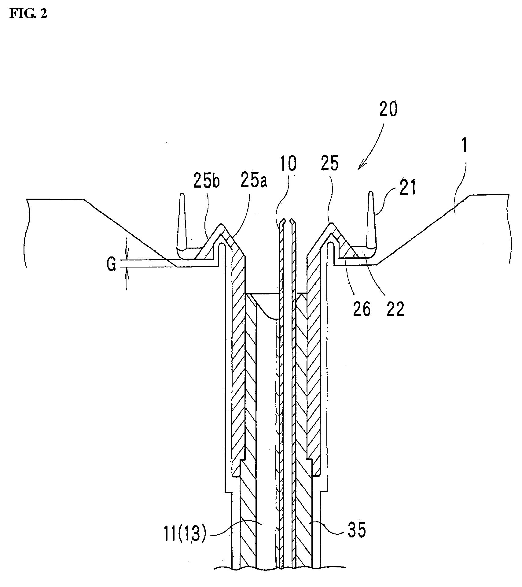
[0073]As illustrated in FIGS. 6 and 7, the inclined surface 25c of the main body 25 of the lift pin plate 20 descends toward the front end of the solution dischargepipe 13. Also, a lower projection part 26′ is provide...
third example
[0082]Hereinafter, a liquid processing apparatus and method according to a third example of the present invention will be described with reference to FIGS. 9 and 10. The liquid processing apparatus and method according to the third example of the present invention as illustrated in FIGS. 9 and 10 are substantially the same as those according to the first example of the present invention as illustrated in FIGS. 1 to 5, except that the shape of the lift pin plate 20 is changed.
[0083]In the third example of the present invention as illustrated in FIGS. 9 and 10, the same drawing reference numerals are used for the same elements as those according to the first example of the present invention as illustrated in FIGS. 1 to 5, and the detailed description thereof will be omitted.
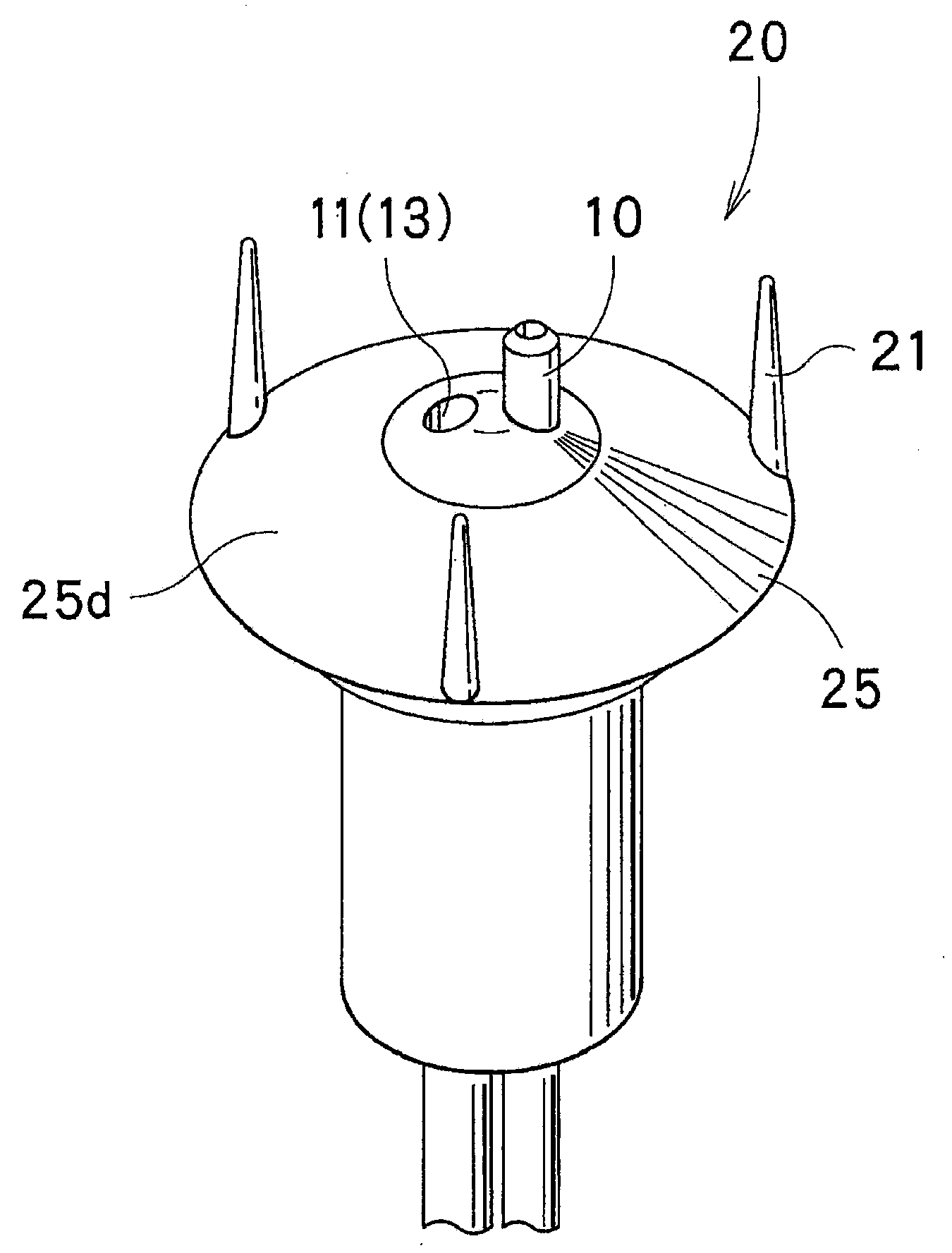
[0084]As illustrated in FIGS. 9 and 10, the inclined surface 25d of the main body 25 of the lift pin plate 20 descends toward the outer side of the edge thereof. Also, a lower projection part 26″ is provided in the...
PUM
Abstract
A liquid processing apparatus, capable of preventing a cleaning solution from remaining on a lifting member of a target object, thereby preventing an attachment of a cleaning solution to an opposite surface of a target object, and preventing an inflow of the cleaning solution into an inertgas supply part to efficiently supply the inert gas to the object, is disclosed. The liquid processing apparatus includes a hollow-shaped support plate to support an object, a hollow-shaped rotary shaft fixedly connected to the support plate, a rotary drive part to rotate the rotary shaft in a predetermined rotating direction, and a lift pin plate arranged in a hollow of the support plate to have lift pins supporting a main body and the processed object. A cleaning solution supply part to supply a cleaning solution and an inertgas supply part to supply an inert gas are extended in a hollow of the rotary shaft. The lift pin plate includes an inclined surface, and the front end of the inert gas supply part is positioned in a position higher than that of the front end of the cleaning solution supply part.
Description
[0001]This application is based on and claims priority from Japanese Patent Application No. 2008-33522, filed on Feb. 14, 2008 in the Japanese Patent Office, the disclosure of which is incorporated herein in its entirety by reference.TECHNICAL FIELD[0002]The present invention relates to a liquid processing apparatus which can clean a target object by supplying a cleaning solution to the target object, while rotating the target object.BACKGROUND[0003]Liquid processing apparatuses include a hollow-shaped bottom plate supporting a target semiconductorwafer (hereinafter referred to as a “wafer”), a rotary shaft fixedly connected to the bottom plate and rotated by a spin motor, a supply pipeline extended in the rotary shaft to supply a cleaning solution to the wafer supported on the bottom plate, and substrate lifting pins ascending to support the bottom of the wafer. One example of the liquid processing apparatuses is disclosed in Japanese Unexamined Patent Publication No. Hei 9-290197...
Claims
Application Information
Patent Timeline
Application Date:The date an application was filed.
Publication Date:The date a patent or application was officially published.
First Publication Date:The earliest publication date of a patent with the same application number.
Issue Date:Publication date of the patent grant document.
PCT Entry Date:The Entry date of PCT National Phase.
Estimated Expiry Date:The statutory expiry date of a patent right according to the Patent Law, and it is the longest term of protection that the patent right can achieve without the termination of the patent right due to other reasons(Term extension factor has been taken into account ).
Invalid Date:Actual expiry date is based on effective date or publication date of legal transaction data of invalid patent.

