
Projector

Inactive Publication Date: 2007-03-01
SEIKO EPSON CORP
View PDF16 Cites 2 Cited by
  • Summary
  • Abstract
  • Description
  • Claims
  • Application Information

AI Technical Summary

Benefits of technology

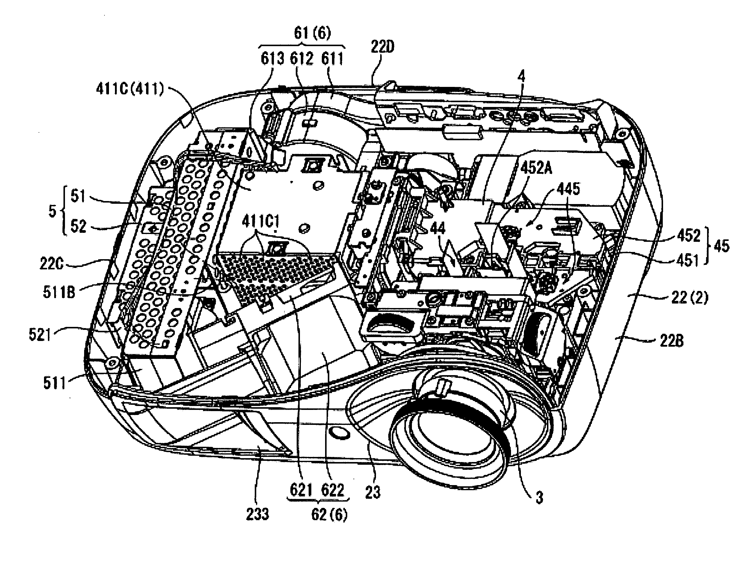
[0010] An advantage of the invention is to provide a projector capable of assuring silentness, blocking the leakage light to the outside of the exterior chassis without making the shape of the ventilation duct more complicated, and preventing the fluctuation on the projected image caused by the exhaust stream.
[0011] A projector according to an aspect of the invention includes an image projection device including a light source device, a optical modulation device that modulates a light beam emitted from the light source device in accordance with image information, and an projection optical device that projects enlarged projection of the light beam modulated by the optical modulation device disposed in a substantially L-shape sequentially from one end to the other end, an exterior chassis accommodating the image projection device, and provided with an air outlet for discharging inside air to the outside formed on an end face on the side of direction of projection, and a ventilation device that discharges air inside the exterior chassis to the outside and includes an axial fan provided with a suction port for sucking air and a discharge port for discharging the sucked air, and disposed in an area inside the exterior chassis and surrounded by the substantially L-shape of the image projection device and adjacent to the light source device so that a discharging direction of air from the discharge port is set towards the projection optical device, and the suction port and the discharge port are set at a predetermined angle with a plane perpendicular to the direction of projection of the projection optical device, and an air outlet duct that is provided with a vertical wall substantially perpendicular to the discharging direction of the air from the discharge port of the axial fan, and bends the air discharged from the discharge port by the vertical wall at an angle of substantially ninety degrees towards a side receding from the projection optical device to lead to the air outlet of the exterior chassis.
[0012] In this aspect of the invention, the ventilation device includes the axial fan and the air outlet duct, and the air outlet duct has the vertical wall substantially perpendicular to the discharging direction of the air from the discharge port of the axial fan. Therefore, the sound generated by the axial fan when the axial fan is driven and proceeding by conducted inside the air outlet duct can be insulated by the vertical wall. Therefore, the sound from the axial fan conducted inside the air outlet duct can be prevented from leaking outside the projector via the air outlet, thus the silentness of the projector can be assured. Further, since the vertical wall is substantially perpendicular to the discharging direction, if the sound from the axial fan is reflected by the

Problems solved by technology

However, since the ventilation device described in JP-A-2003-215711 is configured to have the substantially straight air flow channel from the axial fan to the air outlet, the sound generated from the axial fan while the axial fan is in operation is apt to leak outside the projector via the ventilation duct and the air outlet, thus making it difficult to assure silentness of the projector.
Further, it is necessary to provide the louver to the ventilation duct for blocking the leakage light (the light leaking via the air outlet) to the outside of the exterior chassis or preventing the fluctuation on the projected image caused by the exhaust stream, thus the shape of the ventilation duct is made more complicated, and manufacturing of the ventilation duct is apt to become difficult.
Incidentally, if the air outlet duct is configured as follows, it is difficult to enhance the cooling efficiency of the light source device.
The air discharging efficiency in the ventilation device lowered, and it is difficult to achieve enhancement of cooling efficiency of the light source device.

Method used


Image

  • Projector
  • Projector
  • Projector

Examples


Embodiment Construction

[0040] An embodiment of the invention will hereinafter be explained with reference to the accompanying drawings.

[0041] 1. External Configuration

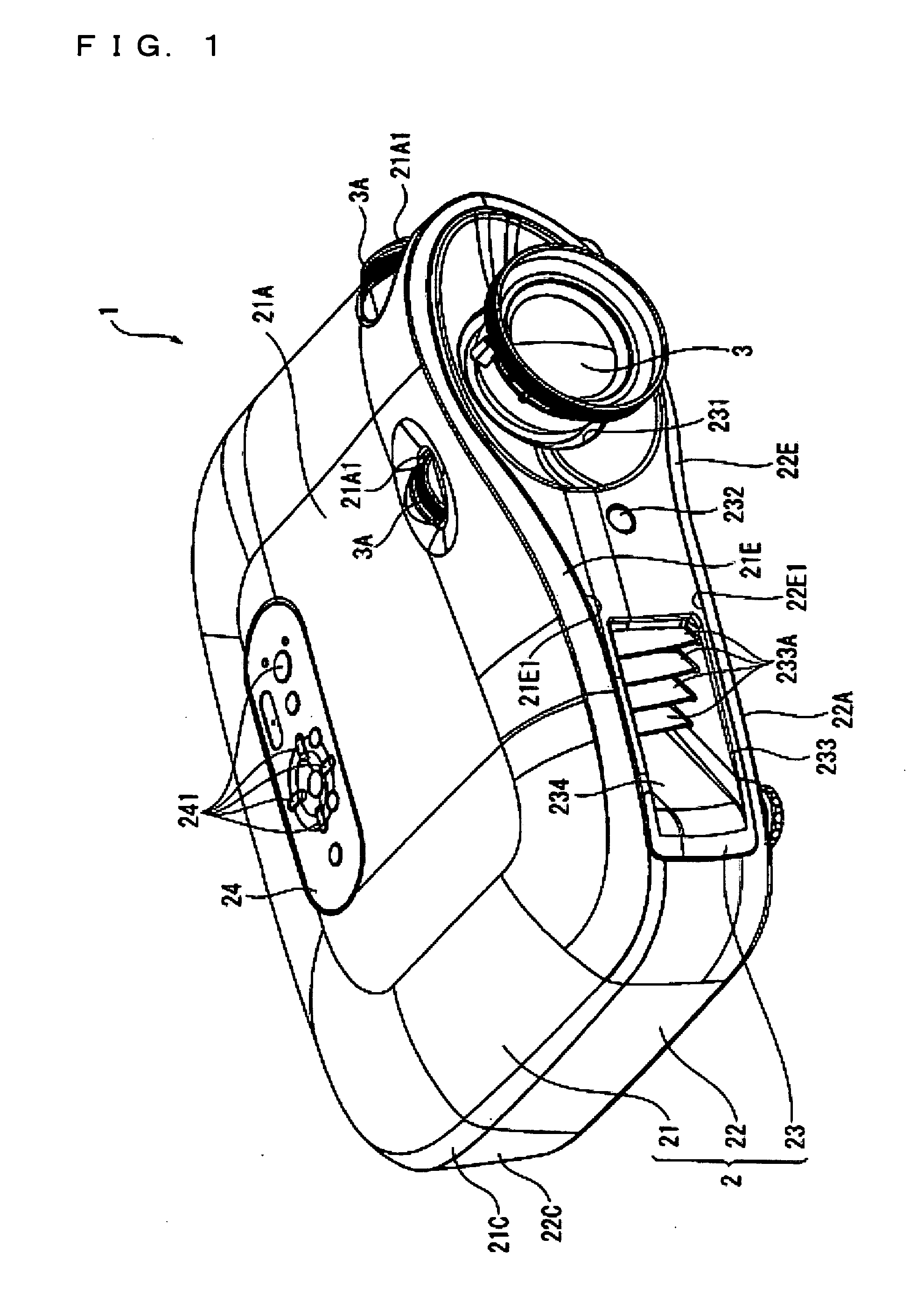
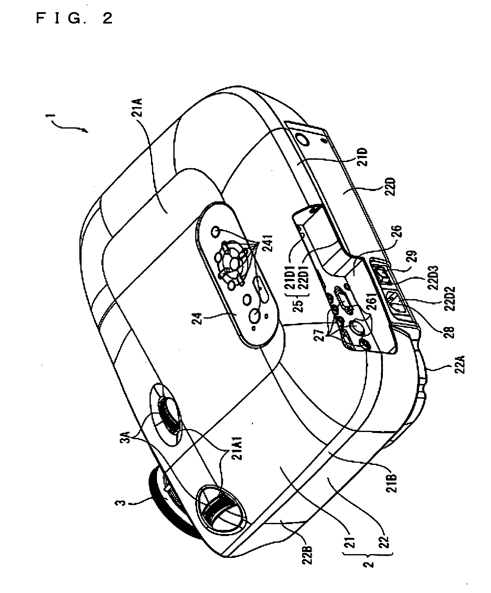
[0042]FIGS. 1 and 2 are the perspective views showing the external appearance of a projector 1. Specifically, FIG. 1 is the perspective view showing the projector 1 viewed from an upper front side thereof. FIG. 2 is the perspective view of the projector 1 viewed from an upper rear side thereof.

[0043] The projector 1 is for forming an optical image by modulating an optical beam emitted from the light source in accordance with image information, and projecting the formed optical image on a screen (not shown) as an enlarged image. As shown in FIG. 1 or 2, the projector 1 is provided with a substantially cuboid shaped exterior chassis 2, and a projection lens 3 as the projection optical device exposed from the exterior chassis 2.

[0044] The projection lens 3 is configured as a set of lenses composed of a plurality of lenses housed in a cylind...


PUM


Abstract

A projector includes an image projection device including a light source device, a optical modulation device that modulates a light beam emitted from the light source device in accordance with image information, and an projection optical device that projects enlarged projection of the light beam modulated by the optical modulation device disposed in a substantially L-shape sequentially from one end to the other end, an exterior chassis accommodating the image projection device, and provided with an air outlet for discharging inside air to the outside formed on an end face of the projection optical device, the end face being located in a direction of projection, and a ventilation device that discharges air inside the exterior chassis to the outside and includes an axial fan provided with a suction port for sucking air and a discharge port for discharging the sucked air, and disposed in an area inside the exterior chassis and surrounded by the substantially L-shape of the image projection device and adjacent to the light source device so that a discharging direction of air from the discharge port is set towards the projection optical device, and the suction port and the discharge port are set at a predetermined angle with a plane perpendicular to the direction of projection of the projection optical device, and an air outlet duct that is provided with a vertical wall substantially perpendicular to the discharging direction of the air from the discharge port of the axial fan, and bends the air discharged from the discharge port by the vertical wall at an angle of substantially ninety degrees towards a side receding from the projection optical device to lead to the air outlet of the exterior chassis.

Description

BACKGROUND [0001] 1. Technical Field [0002] The present invention relates to a projector. [0003] 2. Related Art [0004] In the past, a projector, which has formed an optical image by modulating a light beam emitted from a light source in accordance with image information and projected the optical image as an enlarged image, has been known (see for example, JP-A-2003-215711). [0005] The projector is provided with a ventilation duct unit (a ventilation device) for discharging hot air heated by the light source device operating in a high temperature to the outside of the projector for enhancing cooling efficiency of the light source device. [0006] The ventilation device is provided with an axial fan disposed adjacent to the light source device and for drawing and discharging the air around the light source device and a ventilation duct for leading the air discharged by the axial fan to an air outlet provided to an exterior case (an exterior chassis), and is configured to form a substant...

Claims


Application Information

Patent Timeline
IPC IPC(8): G03B21/18
CPCG03B21/16
Inventor MATSUMIYA, TOSHIOUTAGAWA, TAKESHI
Owner SEIKO EPSON CORP
Learn More