Implantable electrode line

a technology of implantable electrodes and electrodes, which is applied in the direction of external electrodes, internal electrodes, therapy, etc., can solve the problems of complex technical structure, difficult production, etc., and achieves the elimination of reliability, manufacturability and production disadvantages, and easy repositioning and/or releasability. , the effect of easy repositioning and releasability

Inactive Publication Date: 2010-05-27
BIOTRONIK SE & CO KG
View PDF11 Cites 17 Cited by
  • Summary
  • Abstract
  • Description
  • Claims
  • Application Information

AI Technical Summary

Benefits of technology

[0008]The present invention can allow elimination of the aforementioned disadvantages by enabling a secure, easily affixable and releasable anchoring of permanently or temporarily implantab

Problems solved by technology

These devices have the disadvantage of complex technical structure, making production difficult.
There are also serious disadvantages from the standpoint of reliability, manufacturability and production.
It is a major challenge to position such a device at the proper location in a body.
For example, after implanting a measurement sensor, it may be found that the implantation site is unsuitable for providing accurate measurement results.
Repositioning or exp

Method used


Image

  • Implantable electrode line
  • Implantable electrode line
  • Implantable electrode line

Examples


Embodiment Construction

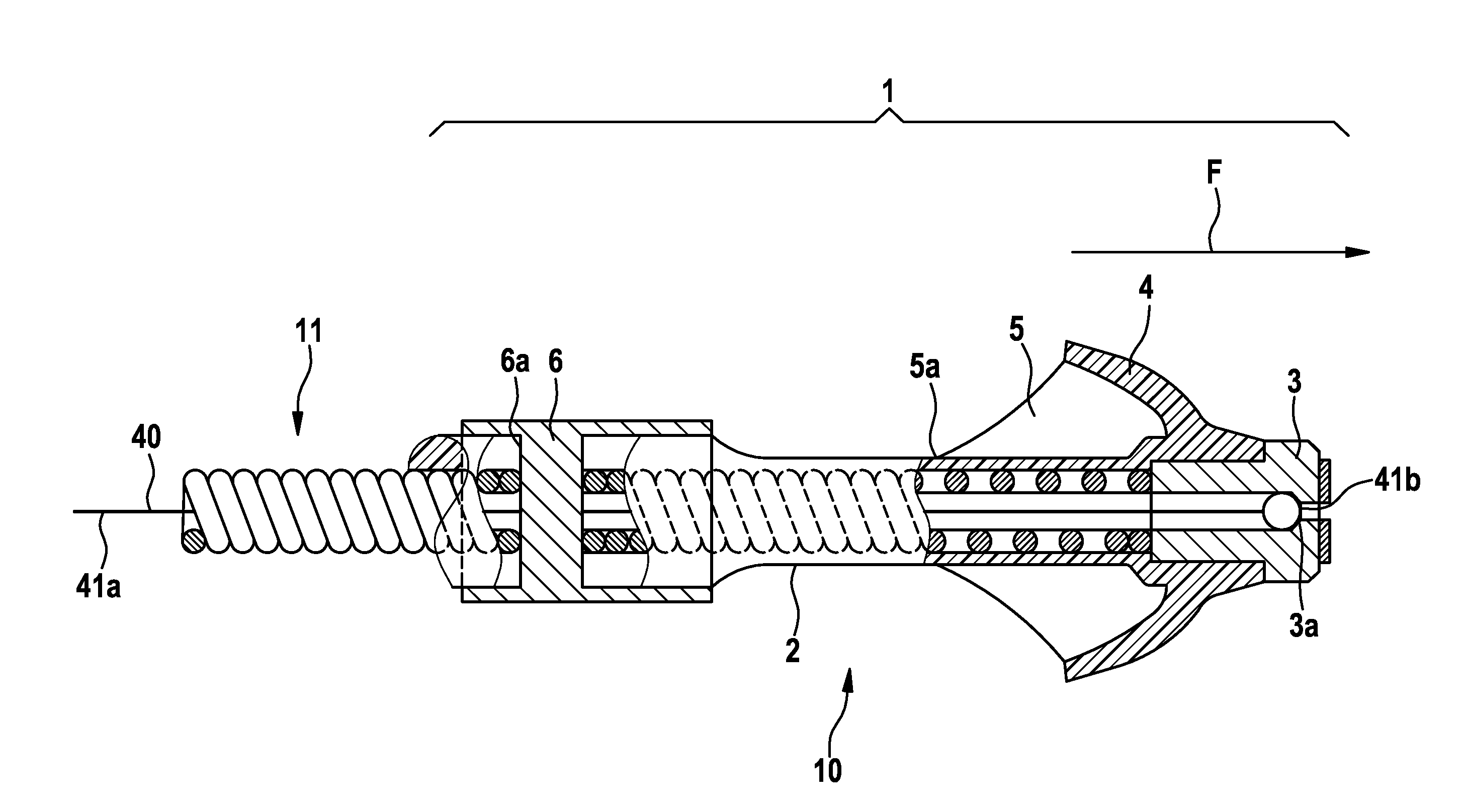
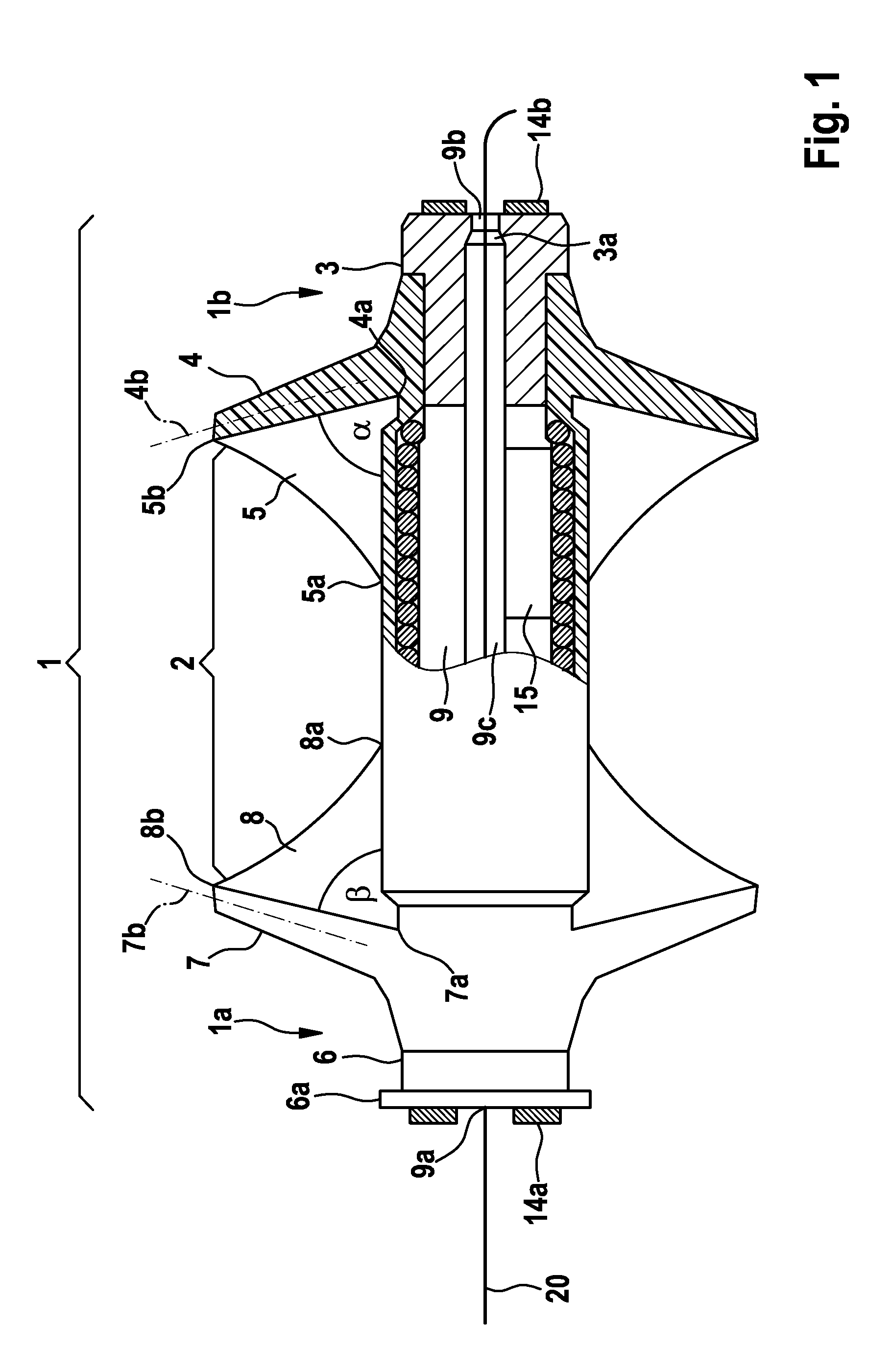
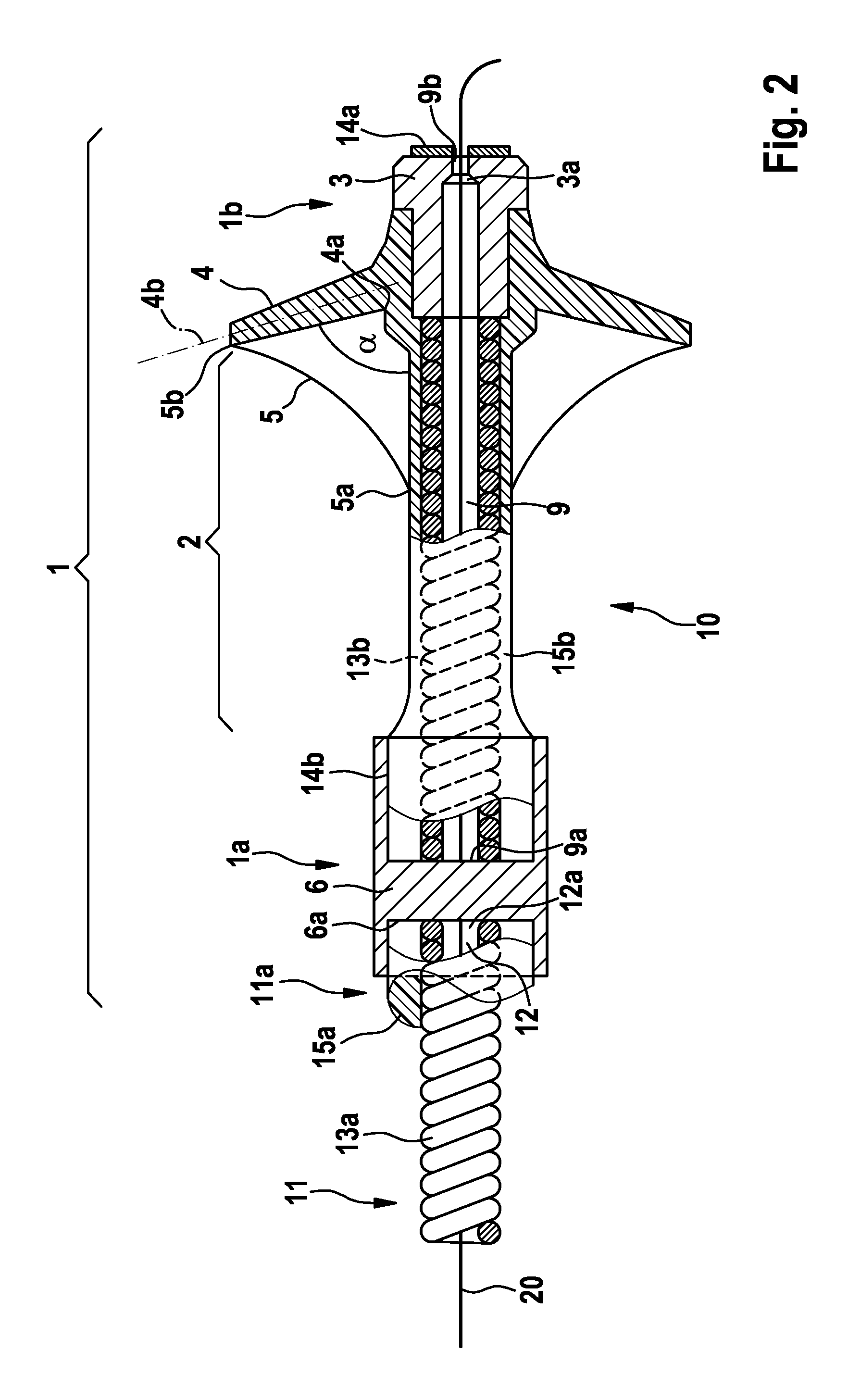
[0056]FIG. 1 shows an exemplary fastening device having a main body 1 with a first end 1a and a second end 1b. The main body 1 includes an extensible and flexible section 2, a first body support 3 on the second end 1b, a second body support 6 on the first end 1a, and a lumen 9 passing through the main body 1. The lumen 9 forms an opening 9b in the first body support 3 and an opening 9a in the second body support 6. The lumen 9 can accommodate components such as a microelectronic unit for analyzing data from a sensor for blood pressure measurement, a transceiver for data transmission of the data analyzed by the microelectronic unit via far-field or near-field telemetry to a device (not shown here) external to the body, and a power supply. For the sake of simplicity, these components are characterized here collectively as electrically active elements 15. The sensor itself is formed by two sensor elements 14a and 14b on the body supports 6 and 3, which measure the different ambient pre...


PUM


Abstract

A device for fastening permanently or temporarily implantable medical devices includes a main body (1) having a first end (1a) and a second end (1b), a flexible and extensible body section (2) therebetween, and a first inflexible and inextensible body support (3) which is fixedly attached to the body section (2) at the second end (1b) of the main body (1), whereby the extensible section (2) can be converted from an unextended state to an extended state in which it is lengthened in comparison with the unextended state. At least one first flexible finger-shaped anchor (4) protrudes away from the main body (1) and is attached to the first body support (3) at an anchor mount (4a). At least one first flexible retraction device (5) is provided for retraction of a respective first anchoring means (4), wherein the retraction device (5) is connected to the body section (2) and to the anchor (4). On conversion of the body section (2) from the unextended state to the extended state, the retraction device (5) does not expand, so that the respective anchors (4) are moved in the direction of the main body (1).

Description

FIELD OF THE INVENTION [0001]The invention relates to a fastening device for affixing permanently or temporarily implantable medical devices, the fastening device having a main body, at least anchoring means (e.g., a flexible finger-shaped anchor), and at least one flexible inextensible retraction device for retracting a respective anchoring means.[0002]In another aspect, the invention relates to an electrode line having a shaft and a fastening device for affixing permanently or temporarily implantable medical devices.[0003]In addition, the invention relates to a system for converting an extensible section of a fastening device or electrode line between an unextended state and an extended state which is lengthened in comparison with the unextended state.[0004]And finally, the invention relates to a method for moving the at least one anchoring means of the fastening device or electrode in the direction of a main body.BACKGROUND OF THE INVENTION[0005]Electrode lines for implantable me...

Claims


Application Information

Patent Timeline
IPC IPC(8): A61N1/05
CPCA61N1/057A61N2001/058A61N2001/0578
Inventor GEISTERT, WOLFGANGFRANKE, ULRICH
Owner BIOTRONIK SE & CO KG
Why Eureka
Try Eureka