

Slide mechanism and slide-type portable electronic device using the same
a technology of electronic devices and sliding grooves, which is applied in the direction of electrical apparatus construction details, electrical apparatus casings/cabinets/drawers, instruments, etc., can solve the problems of display cover wobble, large gap between slide rails and side surfaces of corresponding sliding grooves, and inability to achieve the desired machining precision
- Summary
- Abstract
- Description
- Claims
- Application Information
AI Technical Summary
Benefits of technology
Problems solved by technology
Method used
Image

Examples
Embodiment Construction
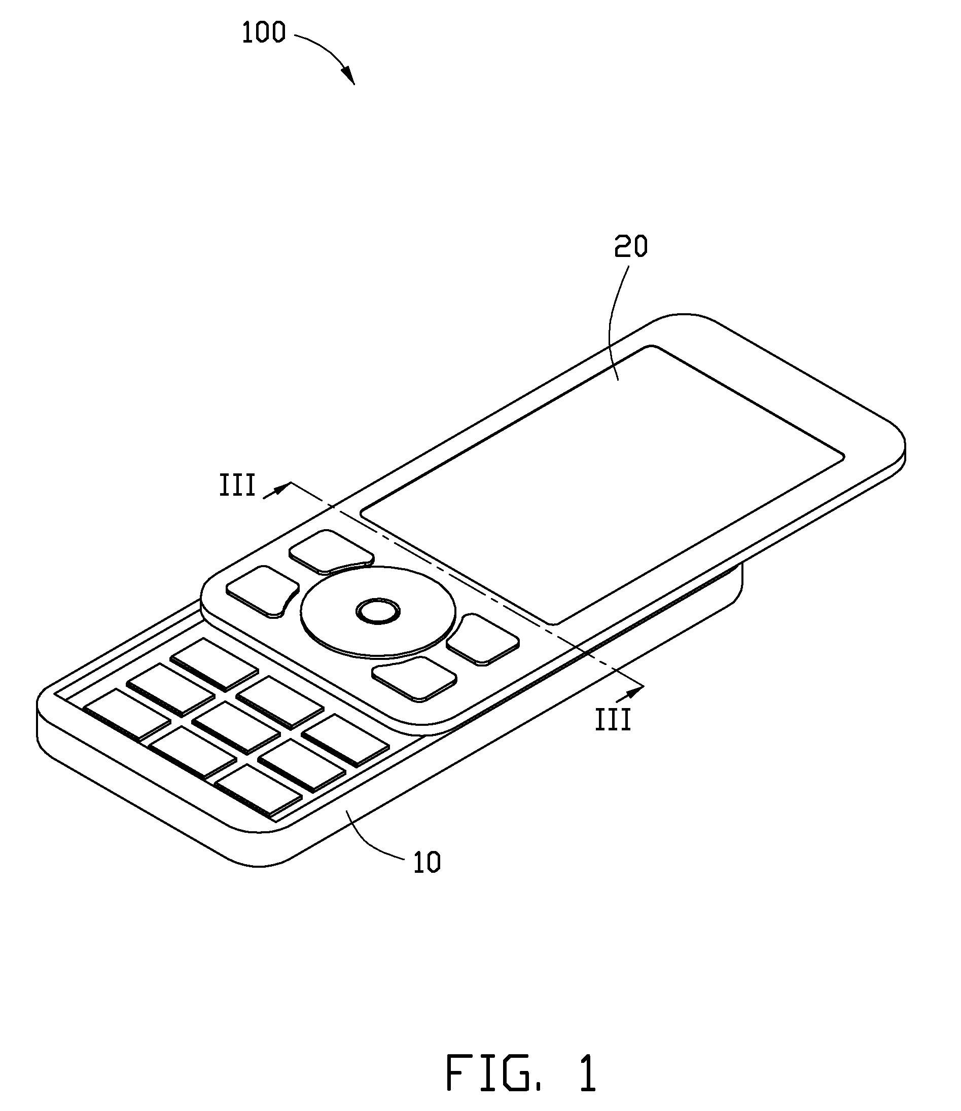
[0012]The slide-type portable electronic device may be a mobile phone, a personal digital assistant, or a media player. Hereinafter, for the purposes of conveniently describing the slide-type portable electronic device, an exemplary embodiment of a slide-type mobile phone is described and illustrated.
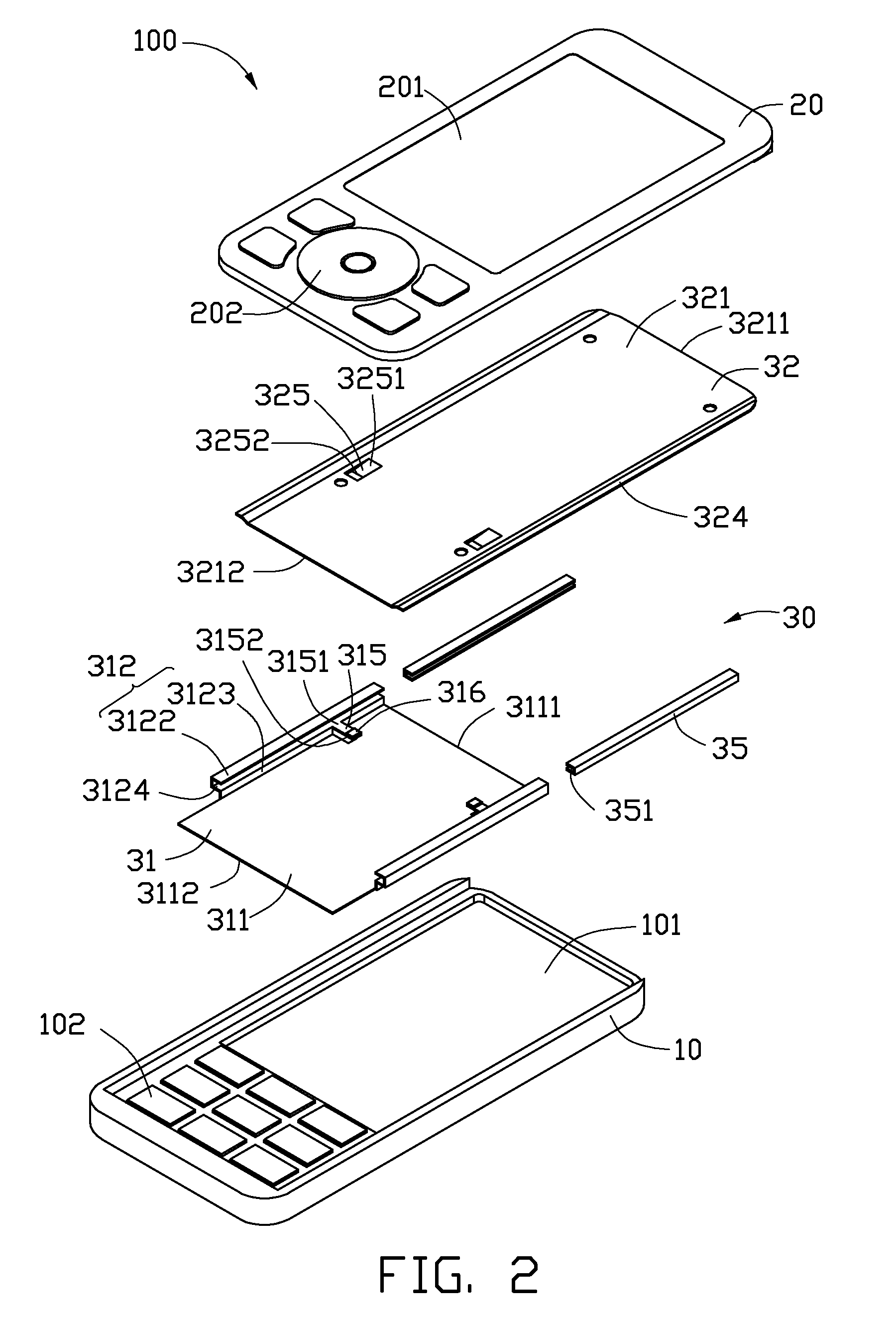
[0013]Referring to FIGS. 1 and 2, a slide-type portable electronic device 100 includes a main body 10, a display cover 20, and a slide mechanism 30. The display cover 20 is slidably assembled on the main body 10 via the slide mechanism 30.
[0014]The main body 10 defines a cavity 101, and includes a plurality of pressing keys 102 positioned on an end of the main body 10 adjacent to the cavity 101.
[0015]The display cover 20 includes a screen 201 positioned on the cover 20, and a plurality of function keys 202 positioned on an end of the cover 20 adjacent to the screen 201.
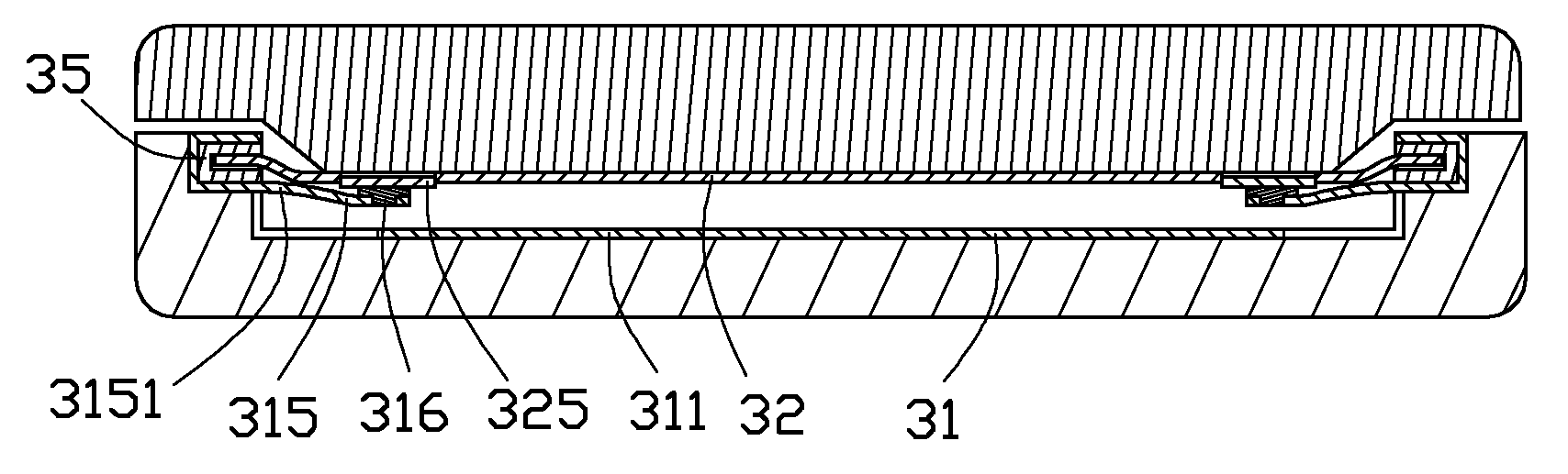
[0016]The slide mechanism 30 includes a rear cover 31 positioned on the cavity 101 of the main body 10, a front cover 3...
PUM
 Abstract
Description
Claims
Application Information