Friction stir welding apparatus and friction stir welding system comprising the same

a friction stir welding and apparatus technology, applied in the field of mechanical manufacturing, can solve problems affecting welding quality and welding precision, and achieve the effects of low inertia, high rigidity, and easy control of the position and posture of the moving platform

Active Publication Date: 2021-02-04
TSINGHUA UNIV
View PDF0 Cites 2 Cited by
  • Summary
  • Abstract
  • Description
  • Claims
  • Application Information

AI Technical Summary

Benefits of technology

[0004]In view of the above problems, an object of the present invention is to provide a friction stir welding apparatus and a friction stir welding system including the friction stir welding apparatus, to solve the problems of low rigidity and thereby poor welding quality and poor welding precision in the existing friction stir welding apparatus.
[0019]Compared with the prior art, the present invention has the following advantages and beneficial effects.
[0020]The present invention adopts a parallel mechanism composed of the first branch mechanism, the second branch mechanism and the third branch mechanism, so that the friction stir welding apparatus of the present invention has four degrees of freedom, and can realize the movement form in two-dimensional rotation and two-dimensional movement of the moving platform, so that it is easier to control the position and posture of the moving platform.
[0021]The present invention has the characteristics of high rigidity, low inertia, high dynamic performance and high precision, and the parallel mechanism has a simple and compact structure, a strong load capacity, a small mass of the moving components, and is easy to achieve high speed movement, thereby the present invention can achieve a precision welding with high requirements on the processing quality and accuracy for jointing the annular seams of the large-scale rocket fuel storage tank barrels in the aviation field.
[0022]The present invention uses a pair of fasteners having adjustable spans to fix the workpiece to be welded, thereby increasing the diameter and overall length of jointing annular seams of the barrels.

Problems solved by technology

At present, as for welding parts with complicated welding surfaces, the existing friction stir welding apparatus generally adopts a series-connected structure so that the apparatus has five-axis linkage processing capability, however it will generate a large forging force during the processing, and the forging force results in the deformation of the series-connected structure, which affects the welding quality and the welding precision.

Method used


Image

  • Friction stir welding apparatus and friction stir welding system comprising the same
  • Friction stir welding apparatus and friction stir welding system comprising the same

Examples


Embodiment Construction

[0025]The embodiments of the present invention will be described below with reference to the attached drawings. Those of ordinary skill in the art may recognize that the described embodiments can be modified in various ways or in combinations thereof without departing from the spirit and scope of the present invention. Therefore, the attached drawings and descriptions are illustrative in nature and are not intended to limit the protection scope of the claims. In addition, in this Specification, the drawings are not drawn to scale, and the same reference numerals denote the same parts. Therefore, the drawings and descriptions are illustrative in nature and are not intended to limit the scope of protection of the claims. In addition, in the present Specification, the attached figures are not drawn to scale, and the same reference numerals indicate the same parts.

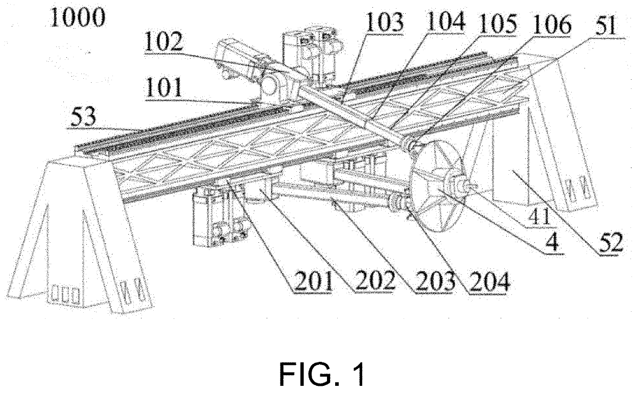
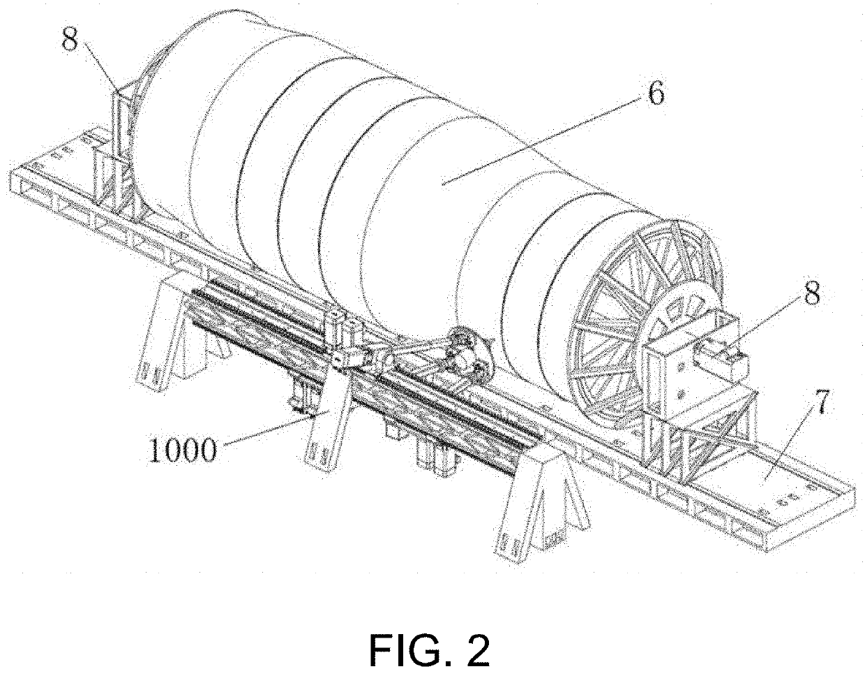
[0026]The present embodiment will be described in detail in combination with FIGS. 1 and 2 in the following.

[0027]FIG. 1 is ...


PUM

PropertyMeasurementUnit
degrees of freedomaaaaaaaaaa
pressureaaaaaaaaaa

Abstract

The presently disclosed technology includes a friction stir welding apparatus comprising a frame, a moving platform and a parallel mechanism composed of three branch mechanisms, wherein a first branch mechanism comprises a first sliding pair, a first revolute pair, a telescopic rod and a first spherical pair connected in sequence. A second branch mechanism and a third branch mechanism both comprise a third sliding pair, a second revolute pair, a third linkage and a second spherical pair connected in sequence. The friction stir welding apparatus has high stiffness, low inertia, high dynamic performance and high accuracy, which can achieve precision welding with high requirements on processing quality and accuracy for jointing annular seams of large-scale rocket fuel storage tank barrels in the aviation field, for example. The presently disclosed technology also includes a corresponding friction stir welding system.

Description

TECHNICAL FIELD[0001]The present invention relates to the field of mechanical manufacturing, in particular, the present invention relates to a friction stir welding apparatus and a friction stir welding system including the friction stir welding apparatus.BACKGROUND ART[0002]Friction stir welding uses a special form of stirring head to proceed forward while rotating, and generates heat by friction between the stirring head and the workpiece to be welded, and the workpiece to be welded is in a thermoplastic state at local position due to the generated friction heat, and the generated friction heat plastically flows from the front end to the rear end under the pressure of the stirring head, thereby the workpiece to be welded is pressure-welded into an integral member. Since the above method is solid-phase welding, the heating process has the characteristics of high energy density and rapid heat input speed. Therefore, the welding deformation is small and the residual stress after weld...

Claims


Application Information

Patent Timeline
Patent Type & Authority Applications(United States)
IPC IPC(8): B23K20/12B23K37/02
CPCB23K20/126B23K2101/06B23K37/0229B23K20/125B23K20/122B23K20/1245B23K20/26B23K37/0538B23K2101/04
Inventor WU, JUNYU, GUANGZHANG, BINBINCUI, HENGCHUNWANG, LIPINGGAO, YING
Owner TSINGHUA UNIV
Why Eureka
Try Eureka