

Pillar structure of a vehicle
a technology of pillars and vehicles, applied in the direction of roofs, transportation and packaging, vehicle arrangements, etc., can solve the problems of increasing the weight of the overall weight of the vehicle, and increasing the weight of the rear wall
- Summary
- Abstract
- Description
- Claims
- Application Information
AI Technical Summary
Benefits of technology
Problems solved by technology
Method used
Image

Examples
first embodiment
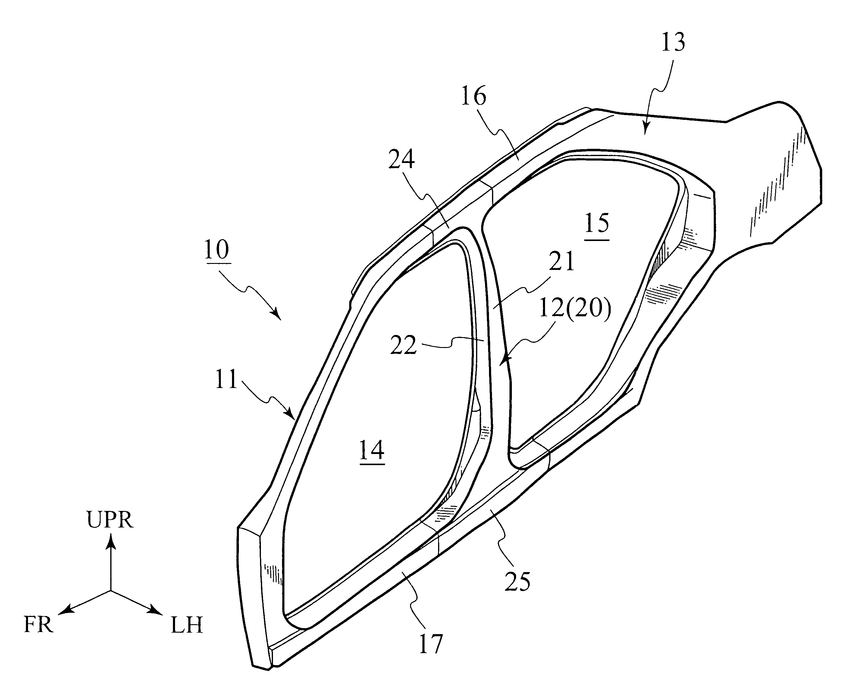
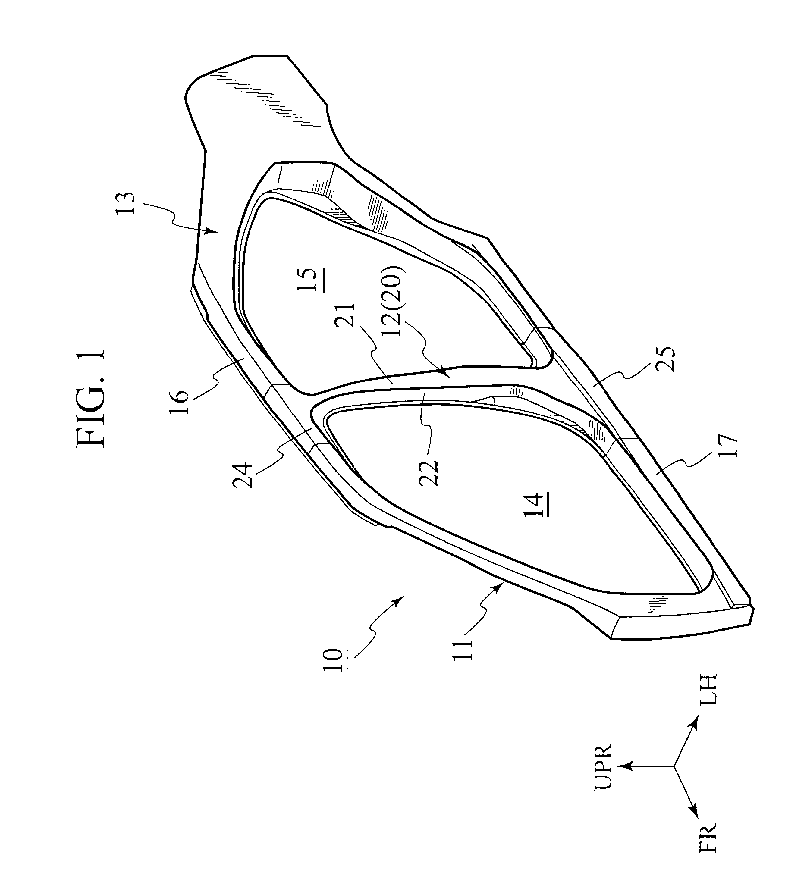
FIGS. 1 to 11 show the present invention. As shown in FIG. 1, in a side structure 10 (transversely outer vehicle body) of a vehicle, openings 14 and 15 for attachment of a front door and a rear door (not shown) are provided between a front pillar 11 and a center pillar 12 and between the center pillar 12 and a rear pillar 13, respectively.
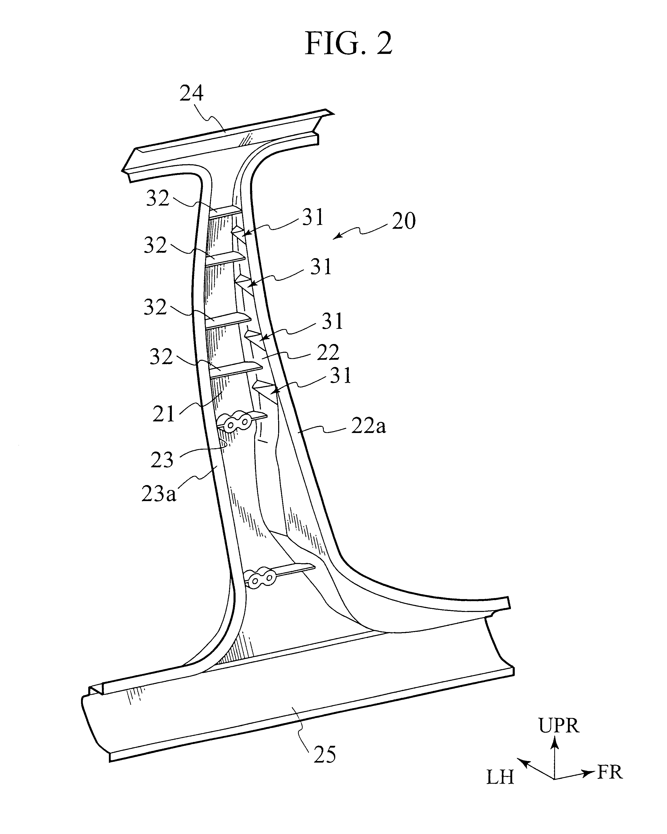
The center pillar 12 is arranged substantially in a center portion of the side structure 10 in a vehicle longitudinal direction and vertically connected across a roof side member 16 in an upper portion of a vehicle body and a side sill 17 in a lower portion of the vehicle body. As shown in FIG. 2, the center pillar 12 includes a pillar member 20 of a structure formed into a channel with a cross section open toward an inside of a compartment.
As shown in FIGS. 3 to 6, the pillar member 20 includes an outer wall 21 (base wall) arranged outward in a vehicle transverse direction, and front and rear walls (side walls) 22 and 23 extended toward the inside...
second embodiment
Accordingly, in the pillar member 20a of the second embodiment, high rigidity portions can be formed continuously from the thick portions 33 formed on the flange portions 22a and 23a to the stiffening projections 31. Accordingly, the rigidity against the tilt deformation of the front and rear walls 22 and 23 can be increased, and the flexural rigidity of the pillar member 20a can thus be increased. Moreover, such portions increasing in thickness allow the molten metal to flow more smoothly and casting ability to be improved. Therefore, influence of variation in material properties to the products can be minimized.
Next, description will be made for a third embodiment. FIGS. 13 to 17 show the third embodiment of the present invention, and components similar to those in the first embodiment are denoted by the same reference numerals and symbols. The common explanation will be omitted.
The main difference between the pillar member 20b of the third embodiment and the pillar member 20 of t...
fourth embodiment
Specifically, as shown in FIGS. 18 to 22, the pillar member 20c of the fourth embodiment includes inner tapered portions 34 formed to extend in the pillar longitudinal direction in the inside of the front and rear walls 22 and 23, where the outer tapered portions 30 are formed. The inner tapered portions 34 gradually increase in thickness toward the inside of the compartment (upward in FIG. 19) from the central beginning ends of the respective outer tapered portions 30, that is, from the substantially center portion C1 of the width of the front and rear walls 22 and 23 to the distal end thereof, while keeping the outer surfaces 22f and 23f of the front and rear walls 22 and 23 as flat surfaces.
Accordingly, in the pillar member 20c of the fourth embodiment, similar functions to those of the first embodiment can be exerted as a matter of course. Furthermore, as shown in FIG. 19, since the thickness of the walls is increased by forming the inner tapered portions 34 inside the front and...
PUM
 Abstract
Description
Claims
Application Information