Stent with porous membrane and manufacturing method thereof

a technology of porous membrane and stent body, which is applied in the field of stent with porous membrane and manufacturing method thereof, can solve the problems of unsuitable fine pores, unproductive laser punching, and interference with productivity improvement, so as to prevent the in-stent restenosis from deteriorating, smooth expansion, and restrict the collapse and deformation of pores

Inactive Publication Date: 2010-03-18
FUJIFILM CORP
View PDF0 Cites 36 Cited by
  • Summary
  • Abstract
  • Description
  • Claims
  • Application Information

AI Technical Summary

Benefits of technology

[0018]According to the present invention, since the membrane is directly formed on the stent body by dipping, the stent body is smoothly expanded in a radial direction. Since the porous membrane covers the entire surface of the stent body down to, for example, all stent wires, the porous membrane can smoothly follow the expansion of the stent body when used, and hence it is possible to restrict the collapse and deformation of the pores, as compared with a conventional stent. Thus, the function of preventing the in-stent restenosis does not deteriorate. After the wet membrane is formed, the porous membrane is formed by drying the membrane with the use of the water drops as the templates. Therefore, the present invention does not require a high-precision process for covering the stent body with the membrane, which was conventionally necessary, so that it is possible to efficiently manufacture the stent with the porous membrane.

Problems solved by technology

Laser punching, however, is nonproductive, and unsuitable for forming the fine pores with a few micrometers pitch.
However, since the porous membrane covers the peripheral surface of a stent body in a quiescent state at the time of manufacture, radial expansion of the stent body when used stretches the porous membrane.
Thus, covering the stent body with the membrane interferes with productivity improvement.

Method used


Image

  • Stent with porous membrane and manufacturing method thereof
  • Stent with porous membrane and manufacturing method thereof
  • Stent with porous membrane and manufacturing method thereof

Examples


example 1

Practical Example 1

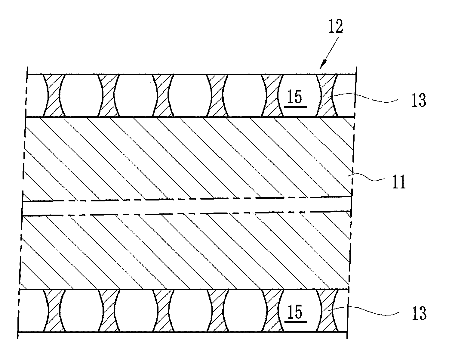
[0097]Next, the practical example 1 of the present invention will be described. In the stent manufacturing apparatus 40 shown in FIG. 5, the membrane with water drops forming process 25 was carried out. After that, the solvent and the water drops 34 were evaporated by the drying process 28 to form the porous membrane 13. The stent body member 20 had an outer diameter of 2 mm and a length of 30 mm. As the dipped polymer, a dichloromethane solution 2.5 mg / ml of a polystyrene-polyisoprene-polystyrene block copolymer is used.

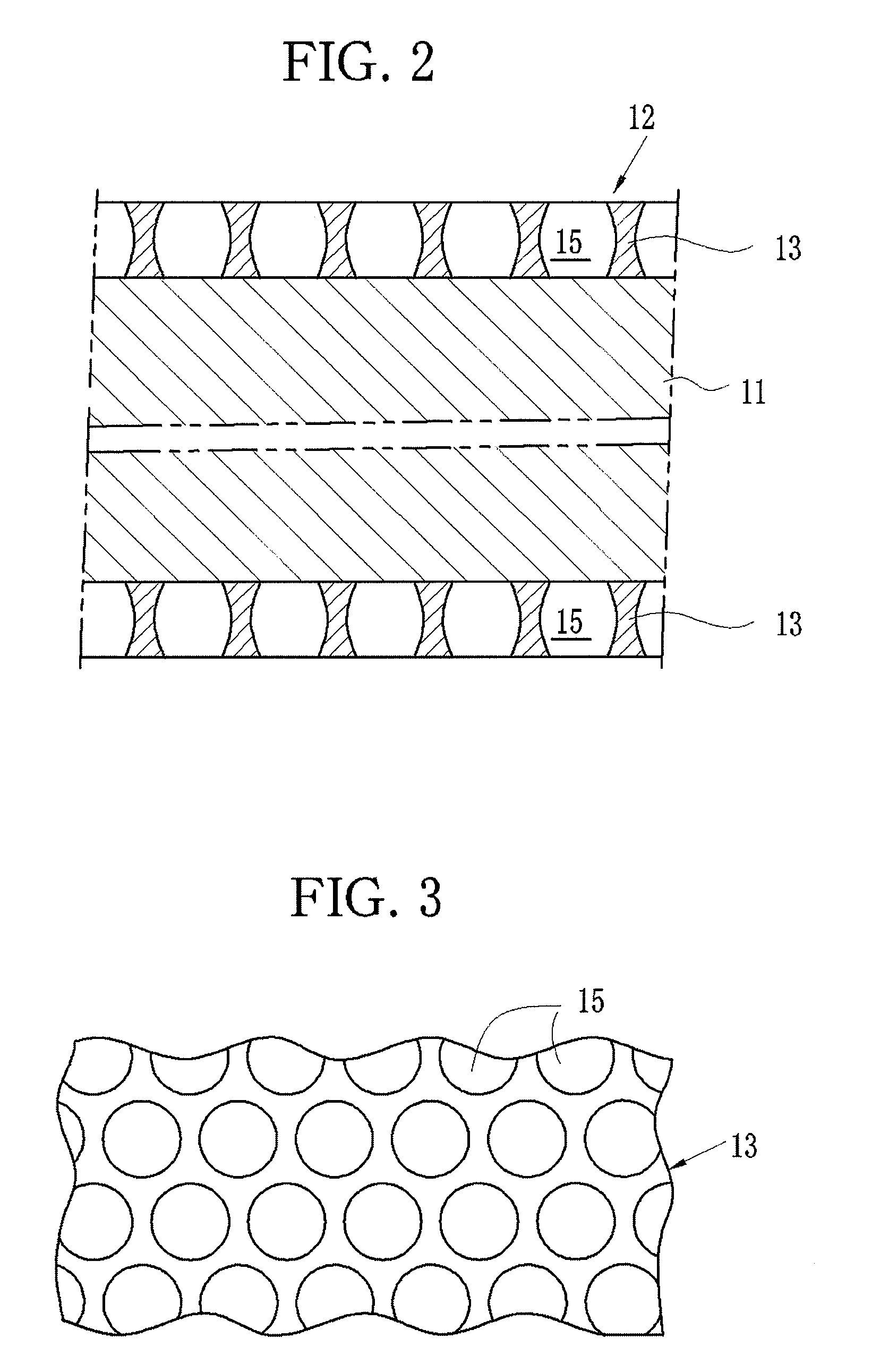
[0098]According to this example, it was possible to almost uniformly manufacture porous membrane 13 in which the diameter of pores was 3.0 μm, the pitch of adjoining pores 15 was 4.0 and the thickness was 1.5 μm. It was verified that the manufacturing method according to the present invention could reduce peeling of the porous membrane 13 and deformation of the pores 15 in expanding the stent body 12, in contrast to a conventional stent in which p...


PUM

PropertyMeasurementUnit
outer diameteraaaaaaaaaa
lengthaaaaaaaaaa
lengthaaaaaaaaaa

Abstract

A dipping bath contains a polymer solution. Stent body members are dipped into the polymer solution. The polymer solution forms membrane on the surface of the stent body member. Humid atmosphere is created around the stent body members with the membrane to condense water vapor into water droplets on the surface of the membrane. After growing the water droplets to water drops, a solvent is evaporated, and the water drops penetrate into the membrane. Then, the water drops are evaporated with leaving pores in the membrane. The water drops function as templates.

Description

BACKGROUND OF THE INVENTION[0001]1. Field of the Invention[0002]The present invention relates to a stent that opens a narrowed blood vessel from inside and is implanted within the blood vessel to keep the blood vessel open, and a manufacturing method of the stent. The present invention especially relates to the stent having porous membrane on its surface and a manufacturing method thereof.[0003]2. Description Related to the Prior Art[0004]A medical instrument called stent is widely used for the treatment of stenosis, strictures and aneurysms in blood vessels. The stent of tubular shape is implanted within the blood vessel such as a coronary artery to keep the artery open.[0005]For the purpose of preventing in-stent restenosis, a covered stent has been developed. The covered stent consists of a metal stent body (bare-metal stent) and polymer membrane with many pores that covers the bare-metal stent (refer to Japanese Patent Laid-Open Publication Nos. 11-299901 and 2005-152004). A dru...

Claims


Application Information

Patent Timeline
Patent Type & Authority Applications(United States)
IPC IPC(8): A61F2/06B05D3/00A61F2/90A61L31/00A61M29/00
CPCA61F2/07B01D67/0009A61F2/90A61F2/89B01D2323/18B01D67/00091
Inventor ITO, KOJUSHIRATSUCHI, KENTAROYAMAZAKI, HIDEKAZU
Owner FUJIFILM CORP
Why Eureka
Try Eureka