Seismic isolation apparatus

Inactive Publication Date: 2006-06-29
BRIDGESTONE CORP
View PDF9 Cites 35 Cited by
  • Summary
  • Abstract
  • Description
  • Claims
  • Application Information

AI Technical Summary

Benefits of technology

[0027] Thus, in the apparatus of the third aspect of the present invention, when a horizontal direction displacement is inputted to the seismic isolation apparatus, the plurality of coil springs with mutually differing outer diameters, which are made of metal with wire material cross-sectional shapes thereof being quadrilaterals, respectively deform to match the input of displacement. However, neighboring faces of the wire materials whose cross-sectional shapes are quadrilaterals touch one another at this time. Thus, the wire materials limitingly abut together. Moreover, the influx material which has been influxed into the outer side laminated body adheres to each of the inner peripheral face of the outer side laminated body and the plurality of coil springs, and this influx material restricts movements of the coil springs to forms in line with the deformation of the outer side laminated body. Therefore, in addition to the wire materials of the coil springs limitingly abutting together, the influx material restricts movements of the coil springs. Thus, a collapse of the coil spring can be automatically prevented.
[0028] Consequently, crushing of the coil spring when large horizontal direction displacements are applied to the seismic isolation apparatus is reliably prevented. Therefore, stable damping ca

Problems solved by technology

However, with a seismic isolation apparatus which simply employs a coil spring of a twin crystal alloy, when a horizontal direction displacement is applied to the seismic isolation apparatus, on the first occasion of displacement, an internal coil spring 122 is twisted in vicinities of two end portions thereof, as shown in FIG. 5B, and is crushed along a direction of a displacement X. As a result, it is not possible to maintain stable damping capabilities, and satisfactory damping effects are not obtained.
However, with a seismic isolation apparatus in which a resin material fills the inside of a coil spring, or the seismic isolation apparatus of JPA '621 or the like, the coil spring that is used instead of a damping alloy is not capable of properly following displacements.
Therefore, in accordance with crushing of the coil spring that is caused by rotation forces within the rubber body, there is an effect that generated forces

Method used


Image

  • Seismic isolation apparatus
  • Seismic isolation apparatus
  • Seismic isolation apparatus

Examples


first embodiment

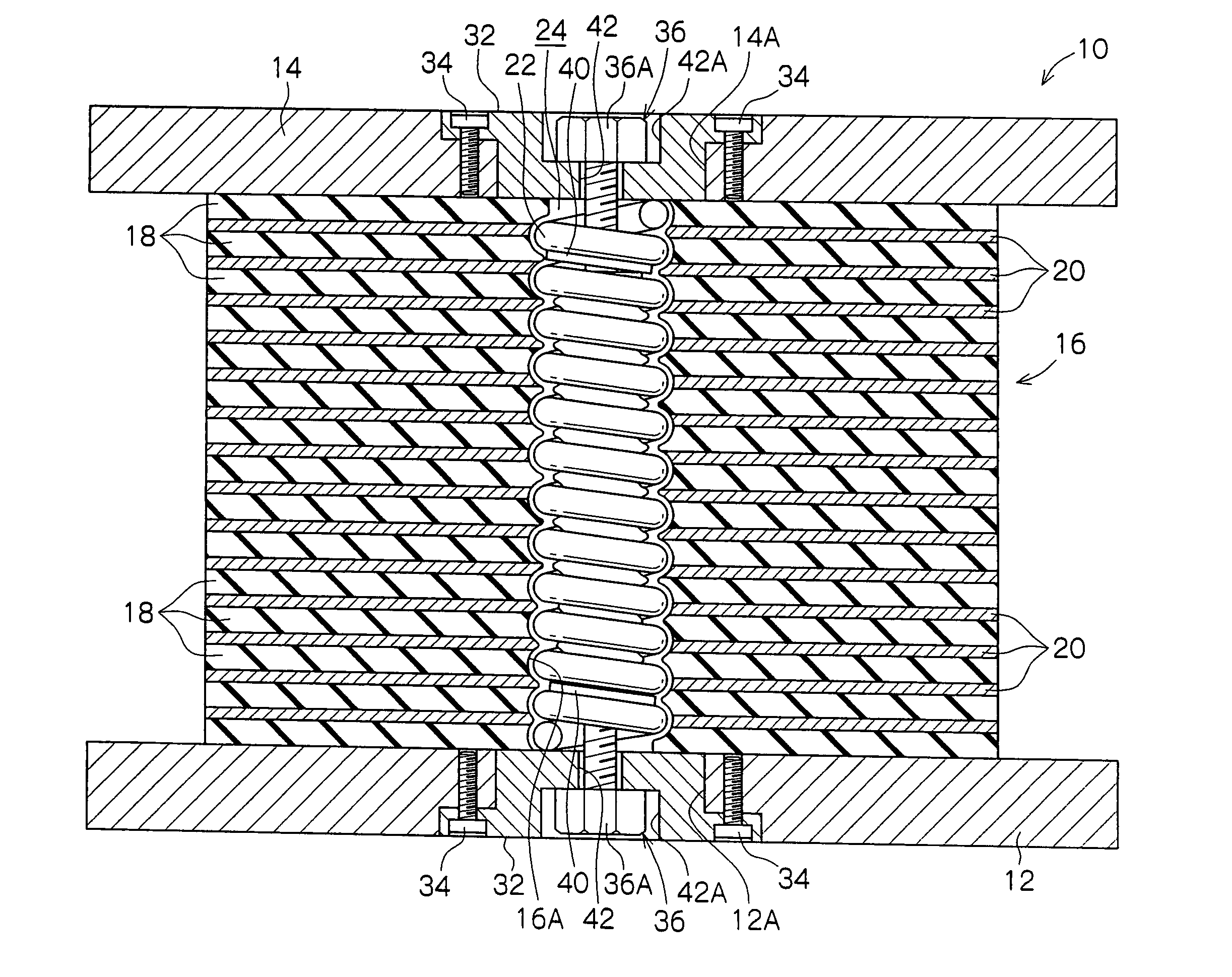
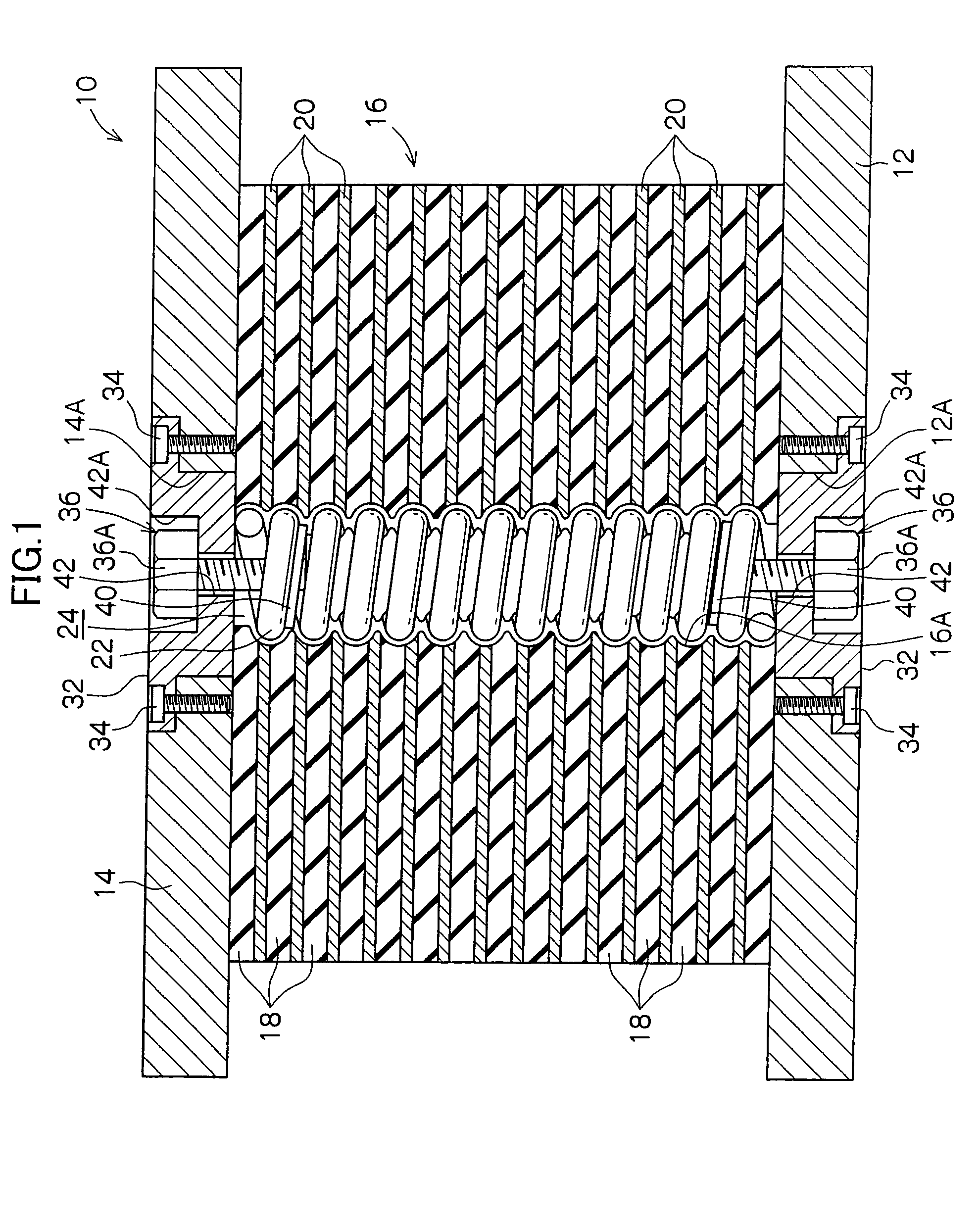
[0055] Embodiments of a seismic isolation apparatus relating to the present invention will be described on the basis of FIGS. 1 to 9B. As shown in FIGS. 1 and 2, top and bottom portions of a seismic isolation apparatus 10 relating to the present invention are structured by connection plates 12 and 14, each of which is formed in a circular plate shape. In this structure, the lower of these, the connection plate 12, abuts against the ground and the upper connection plate 14 abuts against a lower portion of a building.

[0056] An outer side laminated body 16 is disposed between this pair of connection plates 12 and 14. The outer side laminated body 16 is formed in a tubular shape including a tubular cavity portion 24 at a central portion thereof. The outer side laminated body 16 is structured in a form in which a rubber ring 18 fabricated of rubber and a metal ring 20 fabricated of metal are plurally alternatingly disposed. The rubber ring 18 is a first resilient plate, which is formed i...

second embodiment

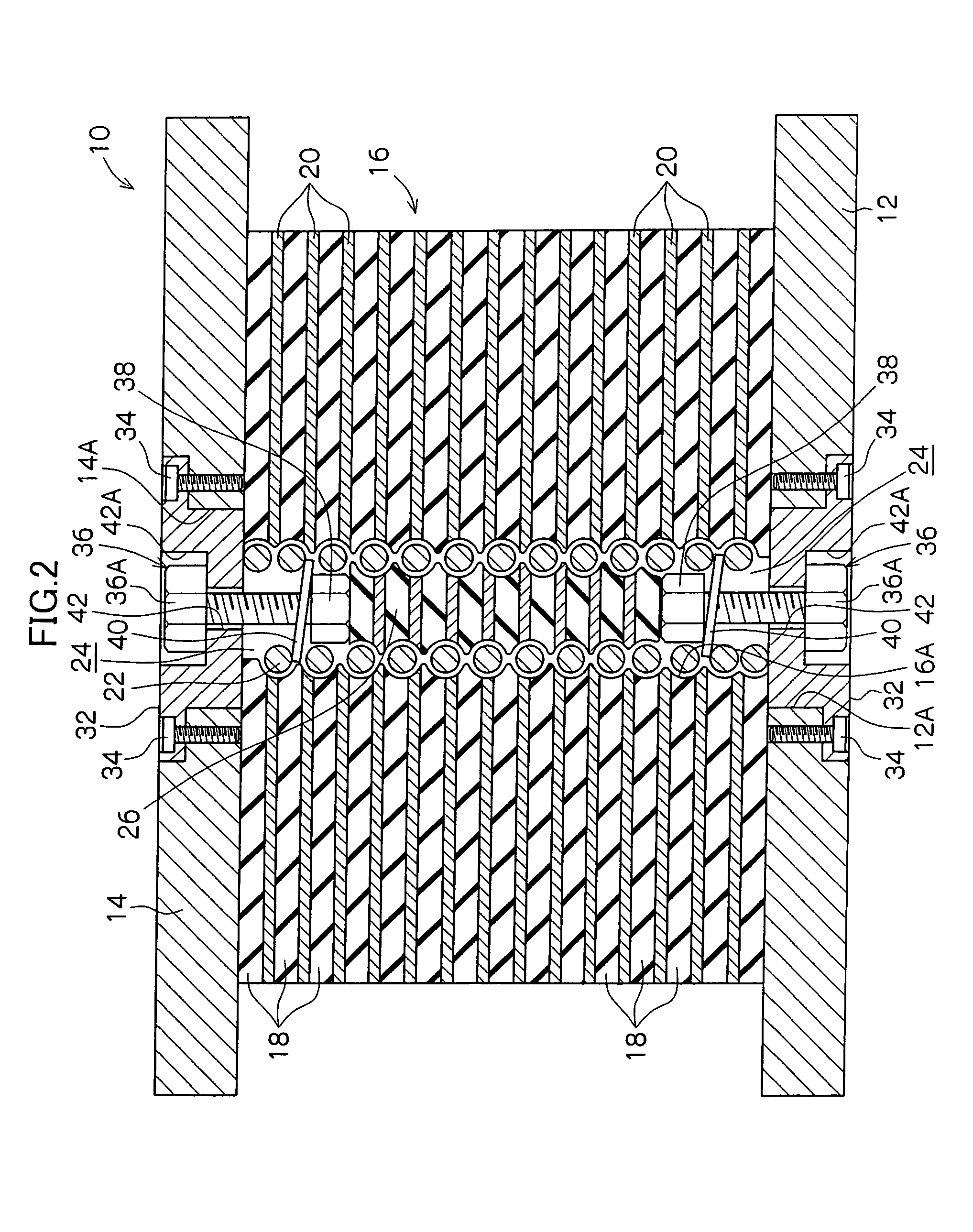
[0092] Note that although the number of coil springs in the second embodiment described above is set to two, there may be three or more coil springs. Furthermore, in the embodiments described above, a twin crystal metallic material is employed as the material of the coil spring(s). However, a different, ordinary metallic material could be employed as the spring material.

[0093] A third embodiment of the seismic isolation apparatus relating to the present invention will be described on the basis of FIGS. 10 to 12. As shown in FIG. 10, top and bottom portions of a seismic isolation apparatus 210 relating to the third embodiment of the present invention are structured by connection plates 212 and 214, which are each formed in a circular plate shape. In this structure, the lower of these, the connection plate 212, abuts against the ground and the upper connection plate 214 abuts against a lower portion of a building.

[0094] An outer side laminated body 216 is disposed between this pair o...

third embodiment

[0114] According to the seismic isolation apparatus 210 of the present embodiment, similarly to the third embodiment, the coil spring 222 is formed by the wire material 222A of the twin crystal metallic material with the cross-sectional shape thereof being a rectangular form, and the coil spring 222 is disposed inside the outer side laminated body 216. In addition, as shown in FIG. 13, the seismic isolation apparatus 210 has structure in which an inner side laminated body 226 is disposed at the inner peripheral side of the coil spring 222. The inner side laminated body 226 is structured in a form in which a metal plate 230 and a rubber plate 228 are plurally alternatingly disposed. The metal plate 230 is an inner side stiff plate which features rigidity and is formed in a disc shape. The rubber plate 228 is an inner side resilient plate which features resilience and is formed in a disc shape.

[0115] That is, in the third embodiment, the coil spring 222 in which the cross-sectional sh...


PUM


Abstract

A seismic isolation apparatus features damping characteristics equivalent to or better than prior art, without burdening the environment. In this seismic isolation apparatus, a cylindrical cavity portion is formed at the middle of an outer side laminated body, which has a form in which respective pluralities of resiliently deformable rubber rings and metal rings for maintaining rigidity are alternately laminated. A helically formed coil spring is disposed in this cavity portion so as to be snugly fitted. An inner side laminated body, which has a form in which respective pluralities of resiliently deformable rubber plates and metal plates for maintaining rigidity are alternately laminated, is disposed at an inner peripheral side of the coil spring.

Description

CROSS-REFERENCE TO RELATED APPLICATION [0001] This application claims priority under 35 USC 119 from Japanese Patent Application Nos. 2004-353888, 2005-016865 and 2005-151982, the disclosure of which is incorporated by reference herein. BACKGROUND OF THE INVENTION [0002] 1. Technical Field [0003] The present invention relates to a seismic isolation apparatus which does not burden the environment and which features damping characteristics better than prior art. [0004] 2. Description of the Related Art [0005] Heretofore, seismic isolation apparatuses which are disposed between buildings and ground that supports the buildings, for reducing shaking due to earthquakes, have been known. In such a seismic isolation apparatus, in addition to a rubber body which serves as a resilient body, a damping alloy for mitigating vibrations associated with the shaking is incorporated. By compound action of these members, shaking due to earthquakes is mitigated, and earthquake shaking is less likely to...

Claims


Application Information

Patent Timeline
IPC IPC(8): E04H9/02
CPCE04H9/022
Inventor SHIZUKU, TAKAHISAKIKUCHI, MASAMIKOBAYASHI, KATSUHIROSAKAI, YOSHIKATSUSEKI, WATARUYOKOI, TAKASHI
Owner BRIDGESTONE CORP
Why Eureka
Try Eureka