Vehicle suspension stop device with reinforced sealing

Active Publication Date: 2007-11-22
SNR ROULEMENTS SA
View PDF5 Cites 36 Cited by
  • Summary
  • Abstract
  • Description
  • Claims
  • Application Information

AI Technical Summary

Problems solved by technology

This technology has the disadvantage of inducing friction torque between the rotating parts, known as the drag torque, which is particularly harmful in applications on guiding wheels.
Nevertheless, rising of liquid by capillarity is not ruled out and the seal is not of good quality.
The device and its constituent components are extremely complex.
The perfor

Method used


Image

  • Vehicle suspension stop device with reinforced sealing
  • Vehicle suspension stop device with reinforced sealing
  • Vehicle suspension stop device with reinforced sealing

Examples


Embodiment Construction

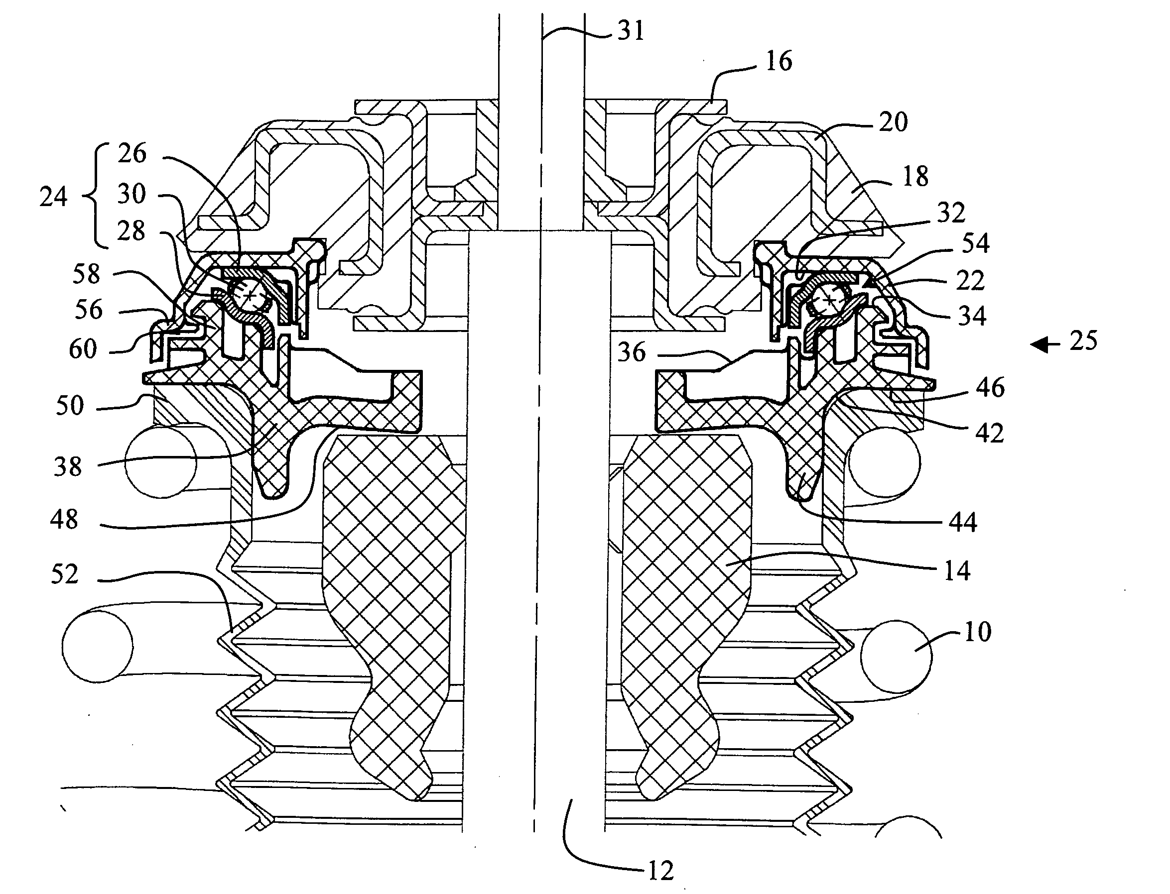
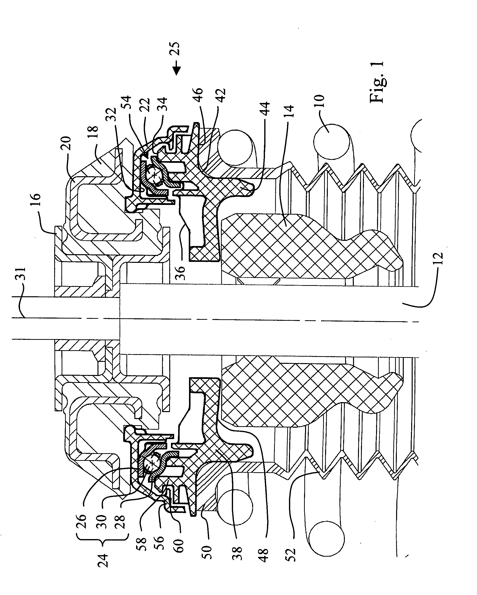
[0037]With reference to FIG. 1, a telescopic suspension strut comprises a coil spring 10, a telescopic shock absorber of which only the rod 12 is visible and a shock absorbing buffer 14, these elements being arranged between a wheel and the bodywork of a vehicle. The rod 12 of the shock absorber is fixed at its upper end by means of a connecting flange 16 to an elastomer block 18 reinforced by a metal insert 20 and attached continuously in itself to the structure of a vehicle. The elastomer block 18 also constitutes an upper support seat for a cover 22 which houses a ball bearing 24 of a suspension stop 25.

[0038]The bearing 24 is comprised of an upper washer 26 and a lower washer 28, both made of pressed steel and forming oblique contact bearing races for running bodies such as balls 30 or conical rollers. The bearing therefore defines a rotation axis 31 of the stop. The upper washer 26 rests on the base 32 of the cover 22, whereas the lower washer 28 rests on a support area 34 form...


PUM


Abstract

A suspension stop for a suspension strut of a vehicle equipped with a coil spring (10) comprises a rigid thrust bearing (24) equipped with a lower metal washer (28) rotating with respect to an upper metal washer (26), a synthetic material support part (38) designed to transmit the forces exerted by the spring to the lower washer and a cover (22) covering the upper washer and delimiting together with the support part a housing (54) for the bearing. The cover is equipped with a skirt (22) delimiting with the peripheral area of the support part an annular labyrinth (60), arranged radially outside the housing and connecting the housing to the outside, with the annular labyrinth successively comprising, from the housing towards the outside, an initial annular head loss of radial play P1, a second annular head loss of axial play P2, followed by a third annular head loss of radial play P3.

Description

TECHNICAL FIELD OF THE INVENTION [0001]The invention relates to a suspension stop for a vehicle suspension strut, particularly for a telescopic suspension strut for an automobile guiding wheel, equipped with a bearing and means of protection of this bearing.FORMER STATUS OF TECHNOLOGY [0002]Conventionally, suspension thrust bearings are housed in two-part casings, closed by sealing lips attached to one of the parts of the casing and rubbing against the other part of the casing, as illustrated in document EP 1 000 781. This technology has the disadvantage of inducing friction torque between the rotating parts, known as the drag torque, which is particularly harmful in applications on guiding wheels.[0003]In order to eliminate this drag torque, it has been proposed to replace the conventional sealing linings with contact-free baffle devices, i.e. devices the rotating elements of which are interlocked with each other, without contact, in order to create a major head loss between the ex...

Claims


Application Information

Patent Timeline
IPC IPC(8): B60G13/00
CPCB60G15/068B60G2202/312B60G2204/1242F16C33/761B60G2204/418B60G2204/45021F16C33/80B60G2204/128F16C2326/05F16C19/10
Inventor CHAMOUSSET, ANTHONYLEBRUN-DAMIENS, LAURENT
Owner SNR ROULEMENTS SA
Why Eureka
Try Eureka