Topology and control method for power factor correction

a power factor and power factor correction technology, applied in the field of switching power supplies, can solve problems such as power-line distortion, electromagnetic interference (emi), and limit system design in terms of the functional load placed on the ac line,

Inactive Publication Date: 2002-02-05
ASTEC INT LTD
View PDF5 Cites 158 Cited by
  • Summary
  • Abstract
  • Description
  • Claims
  • Application Information

AI Technical Summary

Problems solved by technology

Power factors less than about 80 percent can pose barriers to the performance or improvement of many types of electronic devices that operate on direct current, including such devices as personal computers, minicomputers, and appliances using microprocessors.
For example, the high current peaks associated with lower power factors can cause circuit breakers on the AC line to trip, which limits system design in terms of the functional load it places on the AC line.
Additionally, the harmonics associated with the high, non-sinusoidal current peaks often result in power-line distortion, noise, and electromagnetic interference (EMI).
However, conventional control techniques used to achieve this result suffer from a number of drawbacks.
The predominant drawback is that a complex control circuit is needed, as well as bulky and heavy filter components to filter ripple current and to meet the EMI specification of the power supply.
The result is a high cost control circuitry and the need to use more printed circuit board (PCB) space, which in turn contributes to higher fabrication costs.
While this control method ensures that the boost converter operates at the boundary of continuous and discontinuous modes of operation, it suffers from three drawbacks.
First, because the duration of T.sub.on is fixed, the ripple current passing through the inductor is large.
Such variable switching frequency control is usually undesirable for applications involving telecommunications because of possible interference.
Third, because the control chip and accompanying current sensing circuit are necessary in order to provide power factor correction, the inclusion of these components occupies a significant portion of the PCB area and results in increased size and cost of the power supply.
A key drawback of the average current control method is the high cost of the control circuit.

Method used


Image

  • Topology and control method for power factor correction
  • Topology and control method for power factor correction
  • Topology and control method for power factor correction

Examples


Embodiment Construction

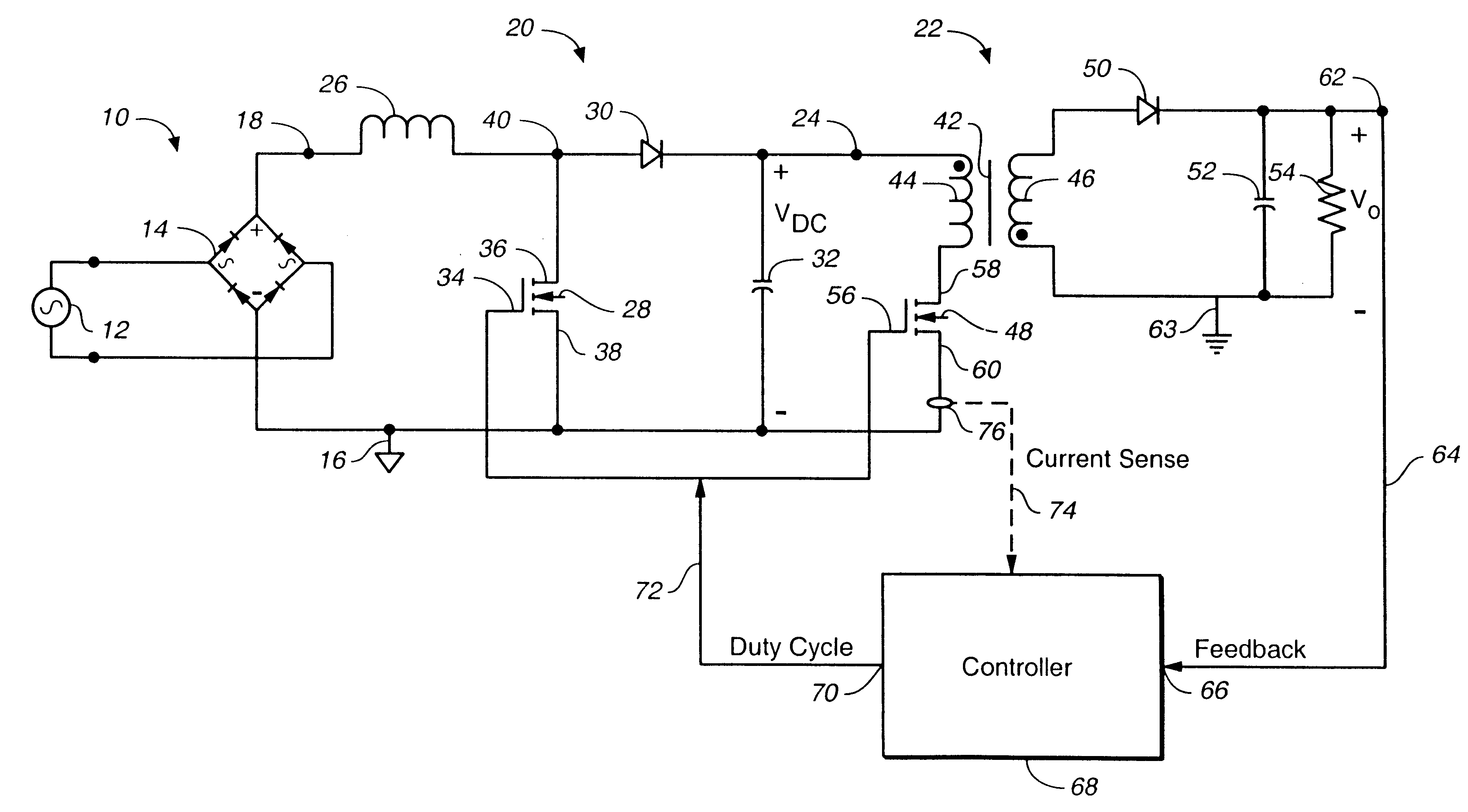
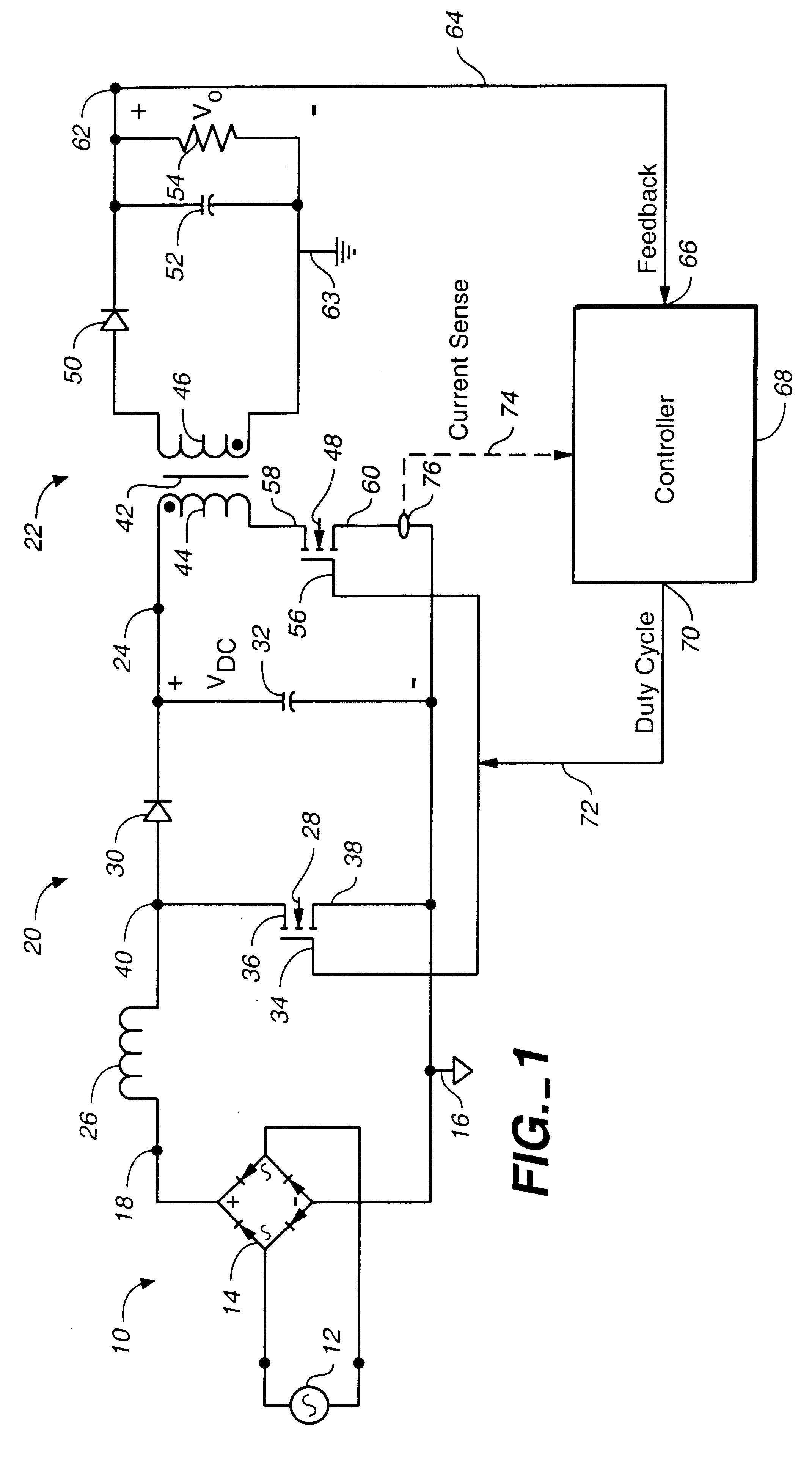
The present invention recognizes that prior art AC-to-DC power supplies having power factor correction require current sensing and signal comparison circuitry in order for the current in the boost converter to be substantially proportional to the input AC voltage. A separate control circuit is required for a second DC-DC converter such as a flyback converter, that provides DC regulation for the output voltage. This results in circuit complexity. By providing a means to obtain power factor correction, yet without such additional circuitry, the AC-to-DC power supply system according to the present invention provides power conversion with power factor correction that is accomplished more cost-effectively and efficiently. This is accomplished by providing a feedback control to simultaneously drive the power switches of the boost and flyback converters. In addition, the boost converter's inductor is selected to provide inductor current that is discontinuous when the instantaneous rectifi...


PUM


Abstract

In a power factor corrected AC-to-DC power supply system, a DC-to-DC power converter is coupled to the output of an AC-to-DC power converter in order to produce a regulated DC output signal from a rectified AC input signal. The AC-to-DC power converter and the DC-to-DC power converter each includes a switch for controlling the operation of their respective power converter. The AC-to-DC converter includes an inductor. The system provides power factor correction for minimizing harmonic distortion by including a controller that receives the regulated DC output voltage as a feedback signal, and in response, produces a series of drive pulses having predetermined constant duty cycle. These pulses are simultaneously fed to each switch, to operate the respective converters alternately between ON and OFF states. When the AC-to-DC converter is driven by a fixed duty cycle of the series of pulses, power factor correction is improved since the current flowing through the inductor is substantially proportional to the waveform of the rectified AC input signal. By preselecting the value of the inductor, the AC-to-DC converter is operable in a discontinuous mode when the instantaneous rectified AC input signal is low and in a continuous mode when the instantaneous rectified AC input signal is high.

Description

1. Field of the InventionThe present invention relates to switching power supplies, and more particularly, to an AC-to-DC power factor correcting power converter comprising a boost power converter coupled to a DC-to-DC power converter where both converters are driven by the same signal derived from the output voltage of the power converter.2. Description of the Prior ArtMany electronic devices, such as computers and many household appliances, require one or more regulated DC voltages. The power for such electronic devices is ordinarily supplied by power converters that convert an AC line voltage into the regulated DC voltages required by the devices.Electrical power converters commonly include a rectifier circuit which converts the AC line voltage to an unregulated DC voltage, also known as a rectified line voltage, and a DC-to-DC converter for converting this unregulated DC voltage into one or more regulated DC output voltages. If a simple rectifier circuit is used, such power conv...

Claims


Application Information

Patent Timeline
Patent Type & Authority Patents(United States)
IPC IPC(8): H02M1/00H02M3/335H02M3/24H02M1/42
CPCH02M1/4225H02M3/335Y02B70/126Y02B70/10
Inventor JAIN, PRAVEEN K.LIU, YAN-FEI
Owner ASTEC INT LTD
Why Eureka
Try Eureka