Wireless battery charging apparatus mounted in a vehicle designed to reduce electromagnetic interference

a charging apparatus and battery technology, applied in the field of vehicles, can solve the problems of unsightly wire trailing between the device and the plug box, drawbacks of wired charger devices, and large items to carry around, and achieve the effect of reducing electromagnetic interference and preventing electromagnetic interference with on-board electronics

Active Publication Date: 2015-04-28
GM GLOBAL TECH OPERATIONS LLC
View PDF16 Cites 57 Cited by
  • Summary
  • Abstract
  • Description
  • Claims
  • Application Information

AI Technical Summary

Benefits of technology

[0010]Embodiments of the present disclosure relate to wireless battery charging systems and wireless battery charging apparatus (also referred to herein as a “wireless charging device” or “wireless charger”) that are implemented within a vehicle for wirelessly charging rechargeable electronic devices. An electromagnetic shield apparatus is provided for reducing electromagnetic interference caused by an on-board wireless battery charging apparatus when it is wirelessly charging a battery of a rechargeable electronic device. These embodiments allow a wireless battery charging system to be implemented within a vehicle by reducing or preventing electromagnetic interference with on-board electronics in the vehicle. This way the wireless charger can be used for wirelessly charging a battery of a rechargeable electronic device without interfering with on-board electronics in the vehicle.
[0011]In one embodiment, a vehicle is provided that comprises electronic components mounted in or on the vehicle, and a wireless battery charging system. The wireless battery charging system comprises a wireless battery charging apparatus mounted within the vehicle, and an electrostatic shield. The wireless battery charging apparatus comprises: a primary coil is capable of inductively coupling magnetic energy for wirelessly charging a rechargeable electronic device. The electrostatic shield is designed to reduce electromagnetic fields from being coupled to the electronic components of the vehicle.

Problems solved by technology

There are numerous drawbacks associated with wired charger devices.
Wired charger devices are bulky items to carry around, and the wire trailing between the device and the plug box can be unsightly.
Moreover, if the trailing wire is snagged or jerked, the wire; the connectors; the socket; or the wall may be damaged.
In addition, because not all manufacturers use the same type of wired charger, if a user forget or looses their cable it's not always easy to find a replacement.
When integrating wireless chargers into a vehicle to develop a vehicle-based wireless charging system, many problems arise since a vehicle is a far different environment than a home or office environment.
One problem that arises in the context of motor vehicles is that they include a wide array of other electronic components, devices and apparatus.
As such, integrating a wireless charger within a vehicle can be problematic since it emits electromagnetic fields when operating to charge a rechargeable electronic device.
The disturbance may interrupt, obstruct, or otherwise degrade or limit the effective performance of electrical apparatus within the vehicle.

Method used


Image

  • Wireless battery charging apparatus mounted in a vehicle designed to reduce electromagnetic interference
  • Wireless battery charging apparatus mounted in a vehicle designed to reduce electromagnetic interference
  • Wireless battery charging apparatus mounted in a vehicle designed to reduce electromagnetic interference

Examples


Embodiment Construction

[0025]As used herein, the word “exemplary” means “serving as an example, instance, or illustration.” The following detailed description is merely exemplary in nature and is not intended to limit the invention or the application and uses of the invention. Any embodiment described herein as “exemplary” is not necessarily to be construed as preferred or advantageous over other embodiments. All of the embodiments described in this Detailed Description are exemplary embodiments provided to enable persons skilled in the art to make or use the invention and not to limit the scope of the invention which is defined by the claims. Furthermore, there is no intention to be bound by any expressed or implied theory presented in the preceding technical field, background, brief summary or the following detailed description.

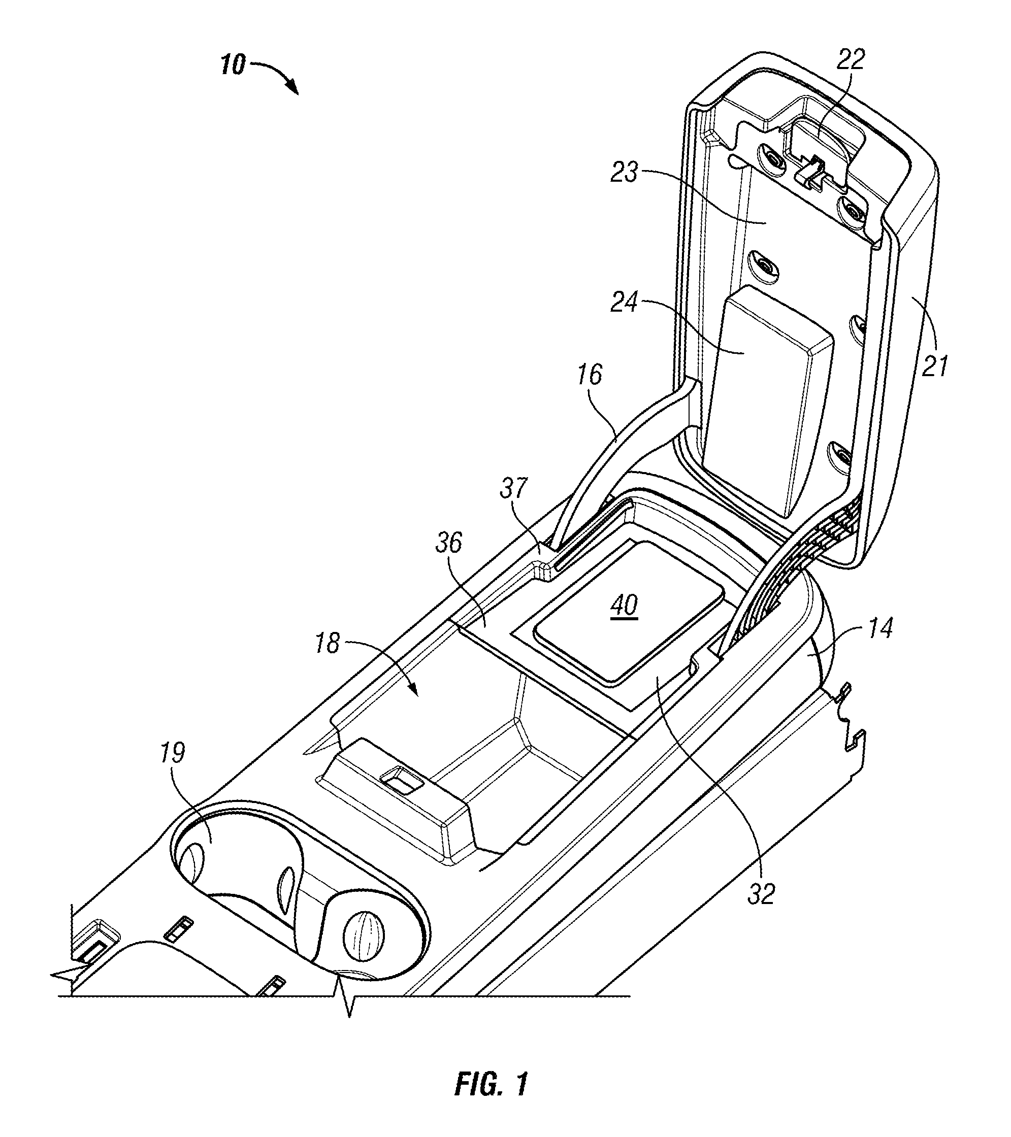
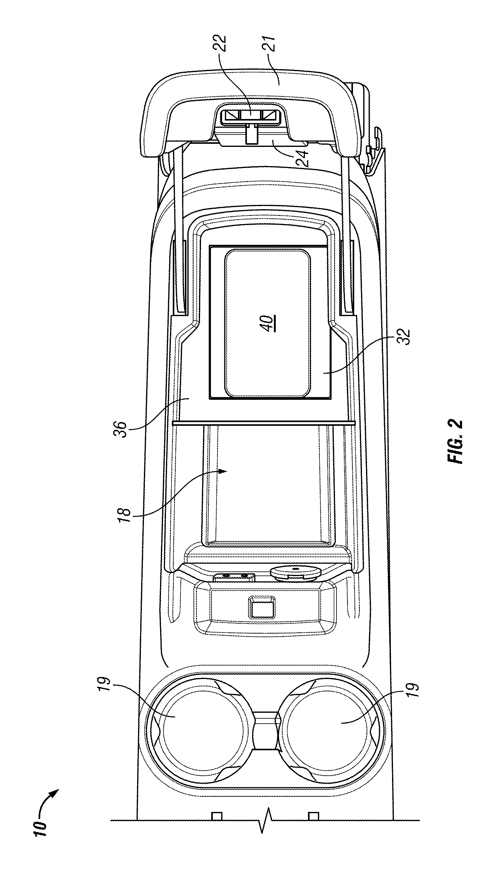
[0026]FIGS. 1, 3 and 4 are perspective views of a floor console armrest assembly 10 in accordance with some of the disclosed embodiments, and FIG. 2 is a top view of a vehicle co...


PUM

PropertyMeasurementUnit
magnetic energyaaaaaaaaaa
electromagnetic fieldsaaaaaaaaaa
electric fieldsaaaaaaaaaa

Abstract

A vehicle is provided having a wireless battery charger that is mounted within the vehicle, and an electrostatic shield for reducing electromagnetic interference radiated by the wireless battery charger.

Description

CROSS-REFERENCE TO RELATED APPLICATIONS[0001]This application claims the benefit of U.S. Provisional Application No. 61 / 523,200 filed Aug. 12, 2011, the contents of which are herein incorporated by reference.TECHNICAL FIELD[0002]Embodiments of the present invention generally relate to vehicles, and more particularly relate to battery charging systems and apparatus implemented within a vehicle for charging rechargeable electronic devices.BACKGROUND OF THE INVENTION[0003]Today a wide variety of electronic devices are commercially available that are powered by power cells commonly referred to as batteries. Many such power cells are rechargeable electrochemical cells also referred to as rechargeable batteries. Electronic devices that include such rechargeable electrochemical cells can be referred to as rechargeable electronic devices. Examples of rechargeable electronic devices include modern mobile communication devices, such as computers, cellular telephones portable / mobile radios, pe...

Claims


Application Information

Patent Timeline
Patent Type & Authority Patents(United States)
IPC IPC(8): H02J7/00B60R16/033H01F27/36H01F38/14H02J5/00H02J7/02H05K9/00
CPCH05K9/002B60R16/033H01F27/36H01F38/14H02J5/005H02J7/0044H02J7/025Y02T90/122H02J2310/46H02J50/402H02J50/80H02J50/70H02J50/10H01F27/363
Inventor SEYERLE, DONALD R.KENDALL, HOWARD E.BALL, LAURA LTRZCINSKI, DAVID J.
Owner GM GLOBAL TECH OPERATIONS LLC
Why Eureka
Try Eureka