System and method for controlling variations of switching frequency

a technology of switching frequency and system, applied in the field of integrated circuits, can solve the problems of large capacitor area of analog circuits, difficult to achieve uniform energy distribution in the frequency band of interest, and difficult to migrate, so as to reduce electromagnetic interference of switch-mode power converters, the effect of reducing the electromagnetic interferen

Active Publication Date: 2006-10-05
ON BRIGHT ELECTRONICS SHANGHAI
View PDF16 Cites 58 Cited by
  • Summary
  • Abstract
  • Description
  • Claims
  • Application Information

AI Technical Summary

Benefits of technology

[0018] Many benefits are achieved by way of the present invention over conventional techniques. For example, some embodiments of the present invention can reduce electromagnetic interference of a switch-mode power converter. For example, the switch-mode converter is an off-line power converter. Certain embodiments of the present invention provide switching frequency variations to a switch-mode power converter. Some embodiments of the present invention avoid a strong single tone at a fixed frequency and the harmonics in a switch-mode power converter. Certain embodiments of the present invention can spread the electromagnetic interference power within a frequency range for a switch-mode power converter. For example, the randomization of the switching frequency can make the EMI power spectrum substantially uniform in a frequency band around a mean switching frequency and the high order harmonics. Some embodiments of the present invention provide frequency variations according to a frequency modulation index Mf. For example, the frequency modulation index Mf is determined by the EMI requirement of the switch-mode power converter.
[0019] Certain embodiments of the present invention use a digital circuit for frequency variation. The digital circuit is portable, and can be easily migrated for different integrated circuit manufacturing processes. Some embodiments of the present invention provide frequency variations to a clock signal by a pseudorandom signal. For example, the pseudorandom signal is a M-sequence signal. Certain embodiments of the present invention use a frequency variation controller including an m-stage M-sequence generator and an N-bit digital-to-analog converter. For example, the m-stage M-sequence generator includes an m-stage linear shift register. In another example, the digital-to-analog converter operates either in the voltage mode or the current mode. In yet another example, the output of the digital-to analog converter is used to control frequency variations of an oscillator in a switch-mode power converter. In yet another example, the clock signal generated by the oscillator is fed into the linear shift register.

Problems solved by technology

A single switching frequency and its harmonics can cause EMI problems.
Accordingly, the analog circuit often needs a large capacitor area and is expensive to implement.
The energy spreading may not be uniform in the frequency band of interest.
But the range of frequency variation is often limited.
Additionally, change of the switching frequency with the power supply voltage often makes the switch-mode power converter difficult to design.

Method used


Image

  • System and method for controlling variations of switching frequency
  • System and method for controlling variations of switching frequency
  • System and method for controlling variations of switching frequency

Examples


Embodiment Construction

[0027] The present invention is directed to integrated circuits. More particularly, the invention provides a system and method for controlling frequency variations. Merely by way of example, the invention has been applied to a power converter. But it would be recognized that the invention has a much broader range of applicability.

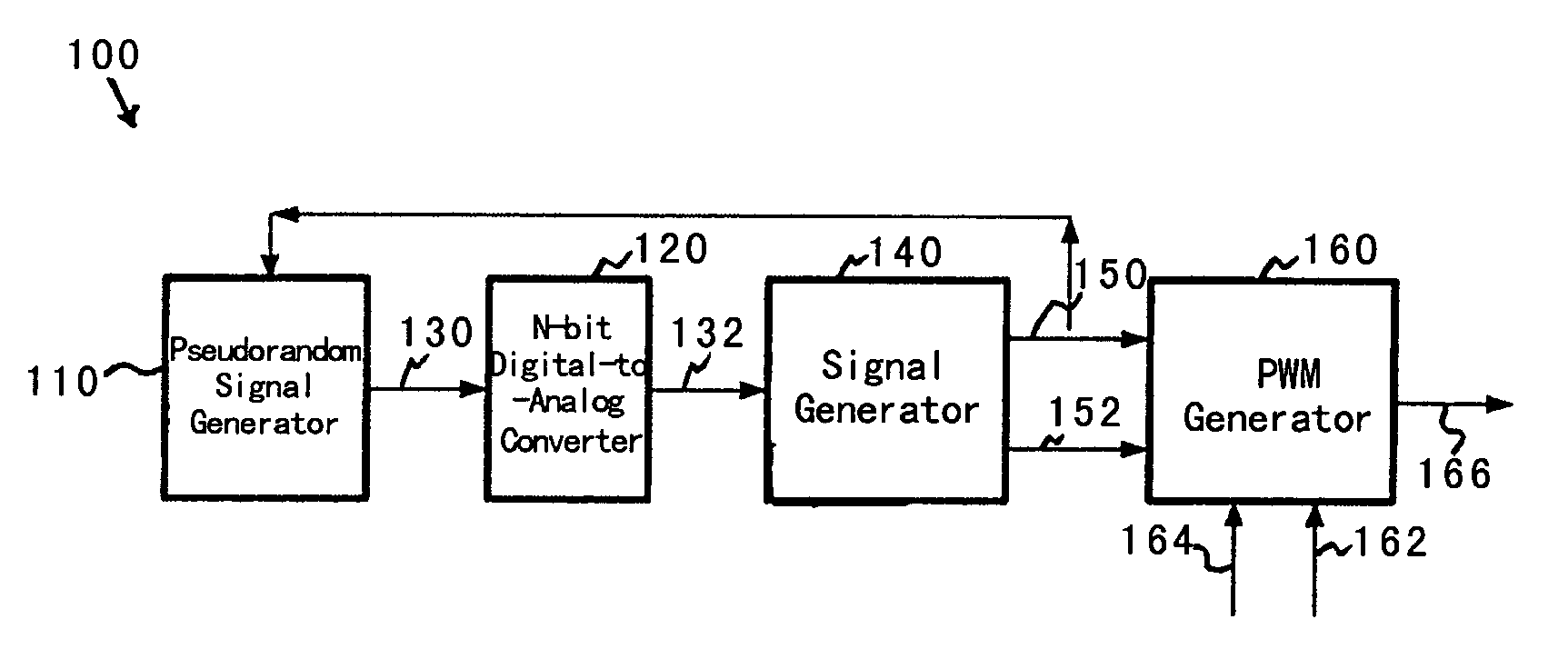
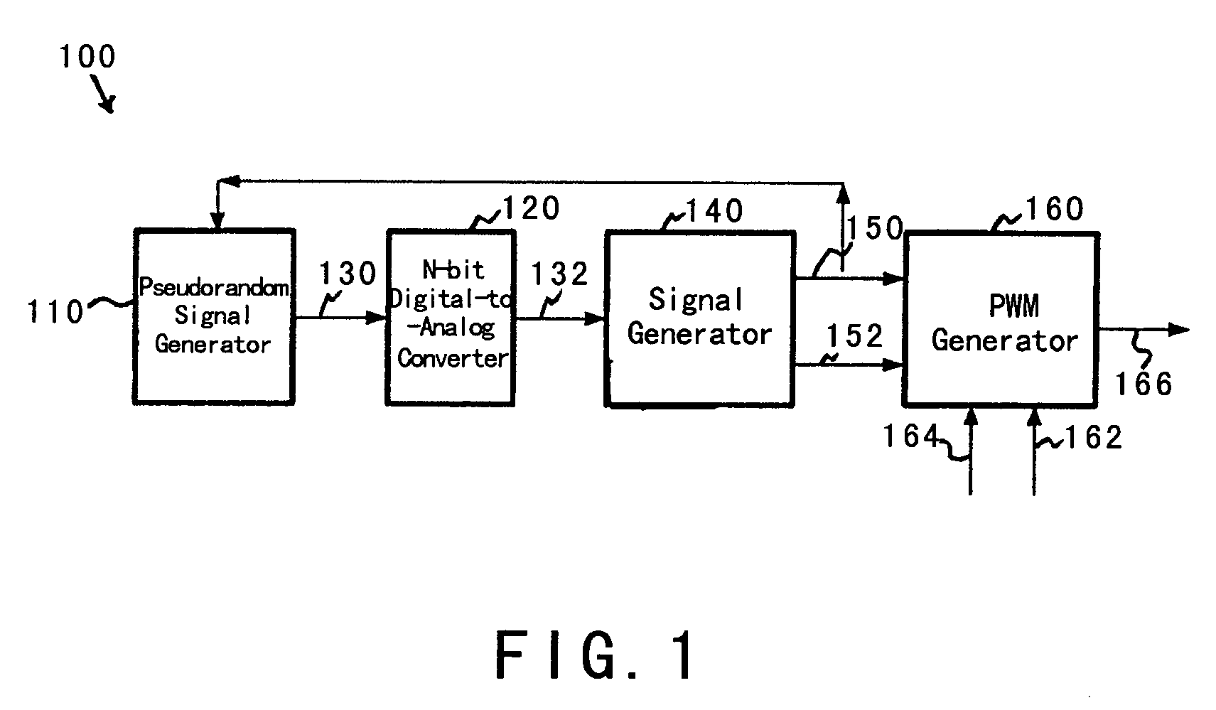
[0028]FIG. 1 is a simplified system for controlling frequency variation according to an embodiment of the present invention. This diagram is merely an example, which should not unduly limit the scope of the claims. One of ordinary skill in the art would recognize many variations, alternatives, and modifications. A system 100 includes a pseudorandom signal generator 110, an N-bit digital-to-analog converter 120, a signal generator 140, and a pulse-width-modulation (PWM) generator 160. Although the above has been shown using a selected group of components for the system 100, there can be many alternatives, modifications, and variations. For example, some of ...


PUM


Abstract

System and method for providing frequency control to a power converter. The system includes a pseudorandom signal generator configured to generate a digital signal. The digital signal is associated with at least an N-bit datum, and N is a positive integer. Additionally, the system includes a digital-to-analog converter configured to receive the digital signal and generate a first control signal, an output signal generator configured to receive the first control signal and generate at least a first output signal associated with a frequency, and a pulse-width-modulation generator configured to receive at least the first output signal. The N-bit datum represents a pseudorandom number.

Description

CROSS-REFERENCES TO RELATED APPLICATIONS [0001] This application claims priority to Chinese Patent Application No. ______ (East IP Ref. No. 05NI2173-1365-SMY), filed Mar. 30, 2005, entitled “System and Method for Controlling Variations of Switching Frequency in Power Converters,” by Inventors Jun Ye, Zhen Zhu, Shifeng Zhao, Lieyi Fang, and Zhiliang Chen, commonly assigned, incorporated by reference herein for all purposes. [0002] The following two commonly-owned co-pending applications, including this one, are being filed concurrently and the other one is hereby incorporated by reference in its entirety for all purposes: [0003] 1. U.S. patent application Ser. No. ______, in the name of Jun Ye, Zhen Zhu, Shifeng Zhao, Lieyi Fang, and Zhiliang Chen, titled, “System and Method for Adaptive Switching Frequency Control,” (Attorney Docket Number 025748-000200US); and [0004] 2. U.S. patent application Ser. No. ______, in the name of Jun Ye, Zhen Zhu, Shifeng Zhao, Lieyi Fang, and Zhiliang ...

Claims


Application Information

Patent Timeline
Patent Type & Authority Applications(United States)
IPC IPC(8): H02M7/00H02M1/44
CPCH02M1/44H03K7/08H02M3/156
Inventor YE, JUNZHU, ZHENZHAO, SHIFENGFANG, LIEYICHEN, ZHILIANG
Owner ON BRIGHT ELECTRONICS SHANGHAI
Why Eureka
Try Eureka