Diagnosis method of defects in a motor and diagnosis device thereof

Active Publication Date: 2010-06-10
IND TECH RES INST
View PDF15 Cites 46 Cited by
  • Summary
  • Abstract
  • Description
  • Claims
  • Application Information

AI Technical Summary

Benefits of technology

[0012]Through the diagnosis method of defects in a motor and the diagnosis device thereof according to the present invention, the diagnosis can be implemented merely with the vibration sensing information and the sound sensing information without other motor parameters. Furthermore, through the diagnosis method of defects in a motor and the diagnosis device thereof according to the present invention, even the vibration sensing information retrieved by the vibration sensing module, such as an accelerometer, can be used as only diagnosis data. Besides, the diagnosis method of defects in a motor and the diagnosis device thereof according to the present invention can be implemented by an embedded system with an advanced RISC machine (ARM) ar

Problems solved by technology

If the motor fails due to certain defects, the manufacture may be interrupted.
However, the number of such professional personnel is limited, and thus the research in the diagnosis for the motor is developed toward establishing an expert system.
In addition, diagnosis tools developed for the professional personnel having the background

Method used


Image

  • Diagnosis method of defects in a motor and diagnosis device thereof
  • Diagnosis method of defects in a motor and diagnosis device thereof
  • Diagnosis method of defects in a motor and diagnosis device thereof

Examples


Example

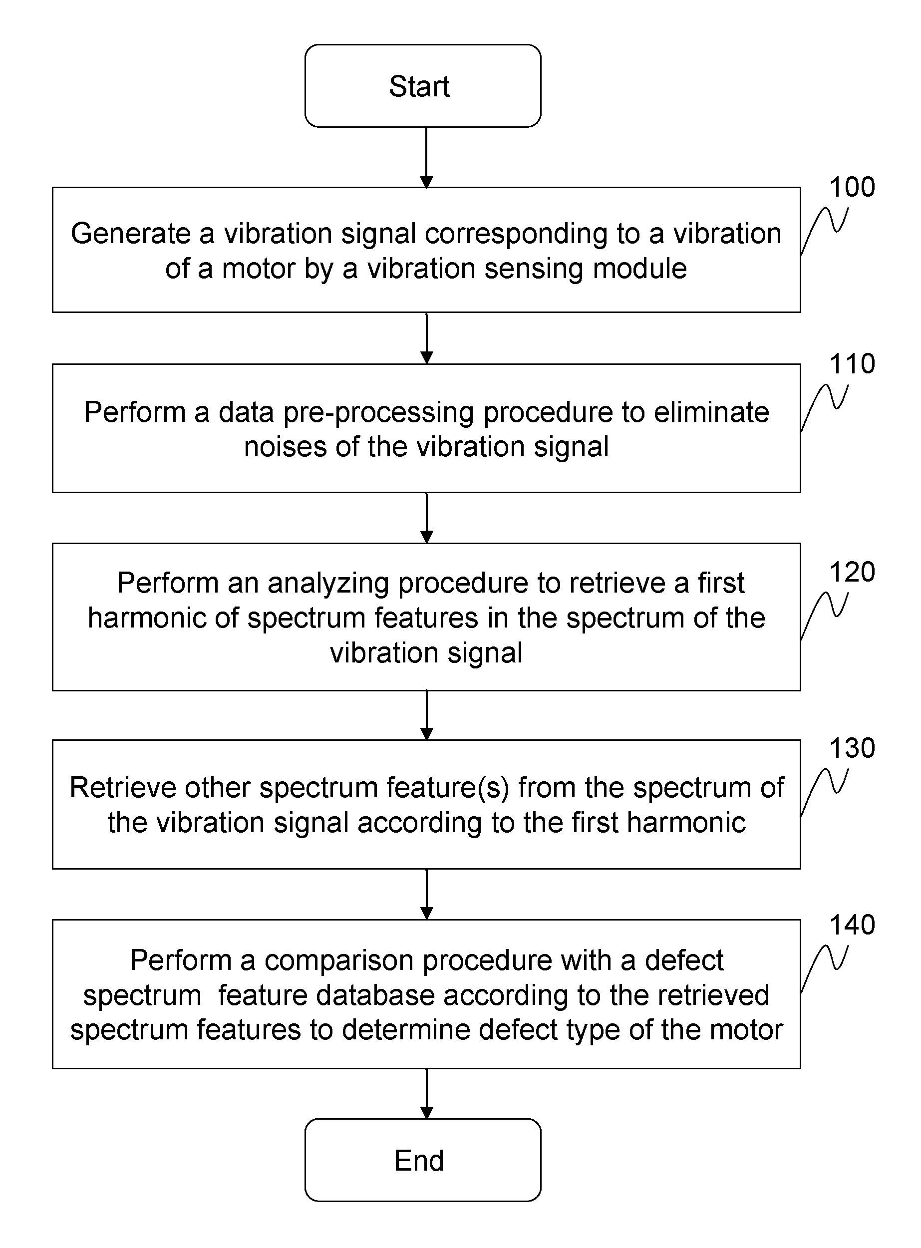
[0022]FIG. 1 is a flow chart of a diagnosis method according to a first embodiment of the present invention. Referring to FIG. 1, the diagnosis method of the defects in the motor equipment of the present invention includes the following steps.

[0023]Firstly, a vibration sensing module is provided to generate a vibration signal corresponding to a vibration of a motor during operation of the motor (Step 100). The vibration sensing module may be, for example, an accelerometer, so as to obtain an acceleration data of the vibration signal.

[0024]Next, a data pre-processing procedure is performed to pre-process the vibration signal, so as to eliminate noises of the vibration signal (Step 110). The data pre-processing procedure includes an integral procedure. The vibration signal obtained by the vibration sensing module is the acceleration data, and the acceleration data includes noises. Thus, after performing the integral procedure to integrate the acceleration data, the noises in the vibra...

Example

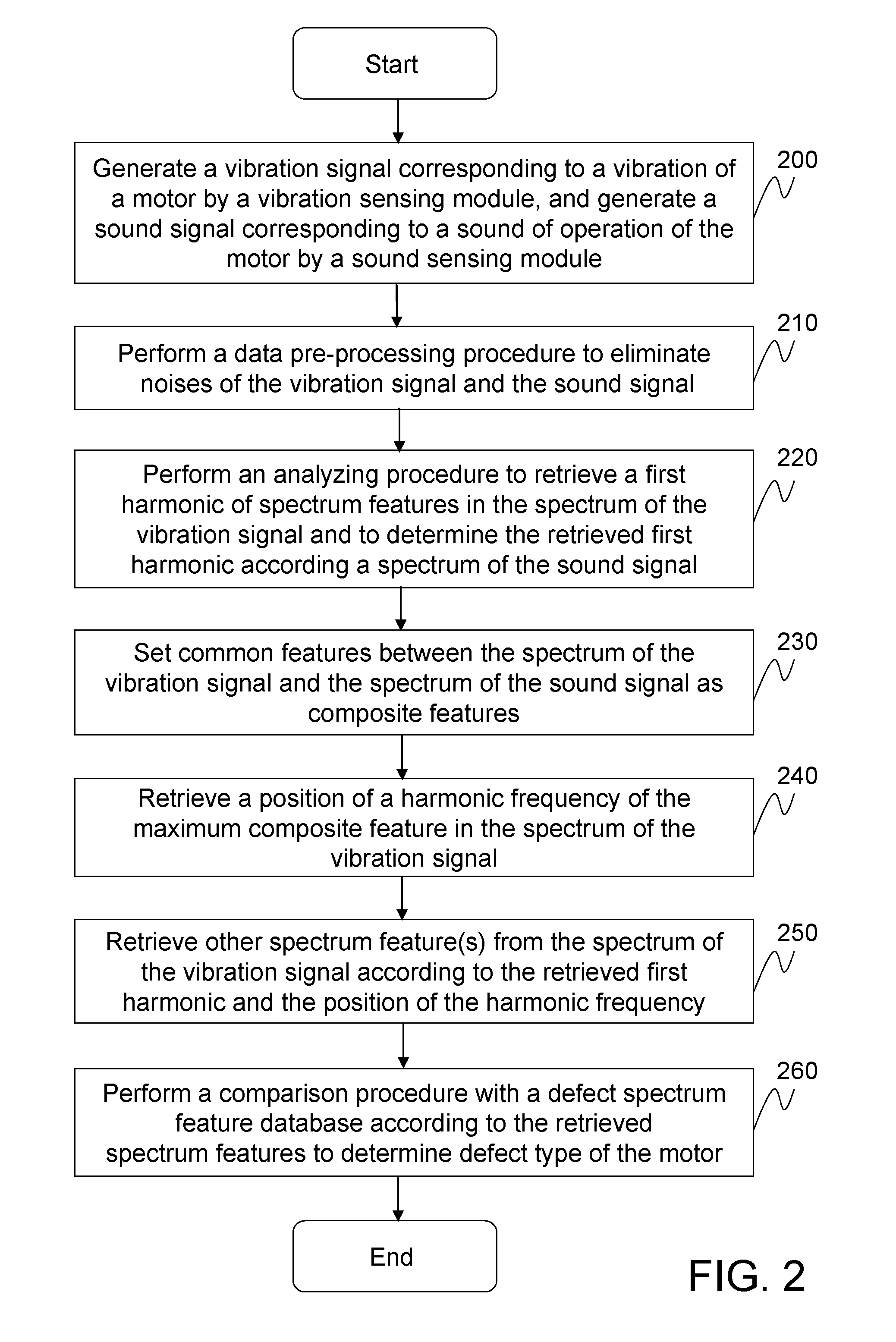
[0030]FIG. 2 is a flow chart of a diagnosis method according to a second embodiment of the present invention. Referring to FIG. 2, the diagnosis method of defects in a motor according to the present invention can be used to diagnose a defect type of a bearing, which includes the following steps.

[0031]Firstly, a vibration sensing module and a sound sensing module are provided to respectively generate a vibration signal corresponding to a vibration of a motor and a sound signal corresponding to a sound of operation of the motor during the operation of the motor (Step 200). The vibration sensing module may be, for example, an accelerometer for obtaining an acceleration data of the vibration signal. The sound sensing module may be, for example, a microphone. The defect types for a ball bearing may be approximately classified into damages to an inner ring, damages to an outer ring, and ball damages. When the defect occurs to the ball bearing, different abnormal sounds and vibrations are ...


PUM


Abstract

A diagnosis method of defects in a motor and a diagnosis device thereof are described. A vibration sensing module can generate a vibration signal corresponding to a vibration of a motor during operation of the motor. Then, a data pre-processing procedure is performed to eliminate noises of the vibration signal. After the data pre-processing procedure, an analyzing procedure is performed to determine a first harmonic of spectrum features in the spectrum of the pre-processed vibration signal. And, other spectrum feature(s) is(/are) retrieved from the spectrum of the pre-processed vibration signal according to the first harmonic. Finally, a comparison procedure is performed with a defect spectrum feature database according to the retrieved spectrum features, so as to determine a defect type of the motor.

Description

CROSS-REFERENCE TO RELATED APPLICATIONS[0001]This non-provisional application claims priority under 35 U.S.C. §119(a) on Patent Application No(s). 097148094 filed in Taiwan, R.O.C. on Dec. 10, 2008 the entire contents of which are hereby incorporated by reference.BACKGROUND OF THE INVENTION[0002]1. Field of the Invention[0003]The present invention relates to a diagnosis method of defects and a diagnosis device thereof, in particular to a diagnosis method of defects in a motor and a diagnosis device thereof.[0004]2. Related Art[0005]The motor has been widely applied in each procedure from maintaining the manufacture to providing a source of a power system. If the motor fails due to certain defects, the manufacture may be interrupted. Thus, it is quite important to monitor and manage an operating status of the motor at any time. In conventional, the task of the diagnosis of the defects in the motor is carried out by experienced professional personnel. These professional personnel are ...

Claims


Application Information

Patent Timeline
IPC IPC(8): G01N29/00G06F15/00G06F19/00
CPCG01H1/003
Inventor FU, CHIA-LINHSU, CHEN-KAIHSU, MING-HSIU
Owner IND TECH RES INST
Why Eureka
Try Eureka