Laying Device

a technology of laying device and traction device, which is applied in the direction of laying cables, mechanical equipment, sewer pipes, etc., can solve the problems of only being suitable to a limited extent, and achieve the effect of avoiding spreading forces or compression forces, directional correction of traction devices, and easy and quick exchang

Active Publication Date: 2010-12-09
DRESDEN UNIVERSITY OF TECHNOLOGY
View PDF15 Cites 2 Cited by
  • Summary
  • Abstract
  • Description
  • Claims
  • Application Information

AI Technical Summary

Benefits of technology

[0033]In a preferred embodiment, the control of the laying device is realized by means of the traction device. Advantageously, a directional correction of the traction device is achieved by pivoting action of the blades. In this connection, the vertical blades are preferably pivotable about a vertical axis and the horizontal blades are preferably pivotable about a horizontal axis. For parallel-guided blades the guiding movement is transmitted onto both blades uniformly in order to avoid spreading forces or compression forces between the blades.
[0034]In a preferred embodiment, the cutting device is arranged on a support device that is attached, in turn, on a traction means. The traction means is provided with the option of pivoting the support device. A guiding movement can thus be realized by pivoting the support device and / or pivoting the vertical blades. A correction of the laying depth is preferably realized in that the horizontal blades are pivoted. In a further preferred embodiment, the laying depth is changed in that the supporting device is positioned at a slant. Since the horizontal blade is arranged in a defined position relative to the support device, the slant of the horizontal blade is changed also in this way. The adjustable laying depth not only makes it possible to circumvent obstacles present in the ground but also makes it possible to reduce the laying depth at predetermined laying positions. This can be used advantageously in order to connect connectors to the laid media lines at laying positions at reduced depth. For example, large areas can be laid in a single process and by parallel arrangement of laying positions with reduced depth these laying positions can be connected with one another by head trenches and in the head trenches collecting lines can be introduced. The area that is thus laid with media lines can therefore be divided into individual fields.
[0035]In a preferred embodiment, the laying device carries ready-made media lines in prepackaged units such as cable drums or exchangeable cassettes during the laying process. These prepackaged units can be easily and quickly exchanged and accelerate the working process. Advantageously, such a prepackaged unit contains approximately 100 m of ready-made media lines, respectively, which corresponds to the average laying length of a laid field.

Problems solved by technology

These devices are suitable only to a limited extent to produce a flat laying pattern of lines because for each laying row one pass across the laying area is to be performed.

Method used


Image

  • Laying Device
  • Laying Device
  • Laying Device

Examples


Embodiment Construction

[0051]The Figures represent preferred embodiments and results of use of preferred embodiments of the device according to the invention without limiting the invention to these embodiments.

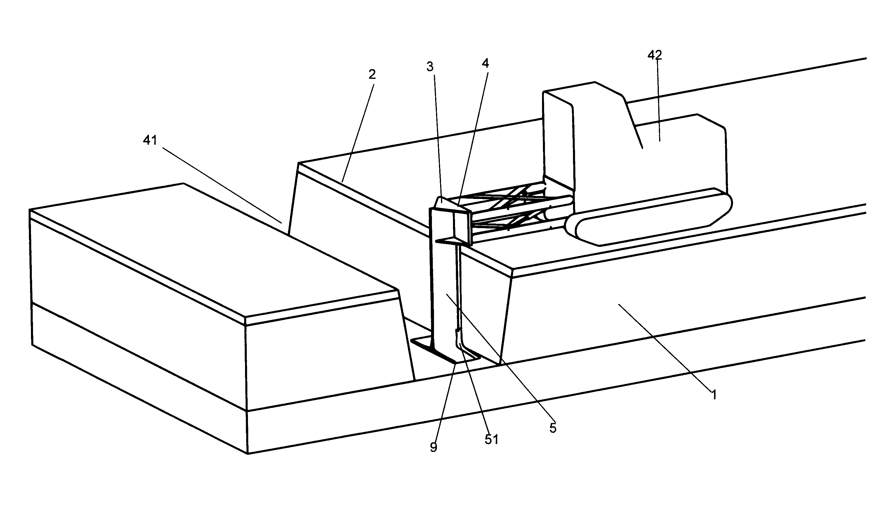
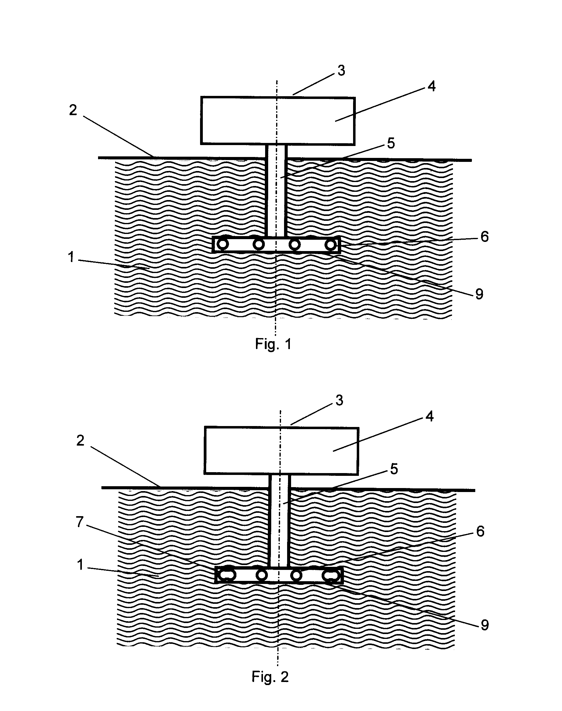
[0052]FIG. 1 shows the principal illustration of the configuration of the laying device (3), comprising a vertical blade (5) and a horizontal blade (9). The movement direction of the device extends perpendicularly into the illustration plane. On the horizontal blade (9) four identical devices (6) for dispensing the media lines are arranged (here for individual axially spaced apart media lines).

[0053]FIG. 2 shows the principal illustration of a laying device (3) as in FIG. 1. Only the two outer devices (7) for dispensing the media lines are designed for two parallel media lines that are not spaced apart. The two inner devices (6) are designed for dispensing individual media lines.

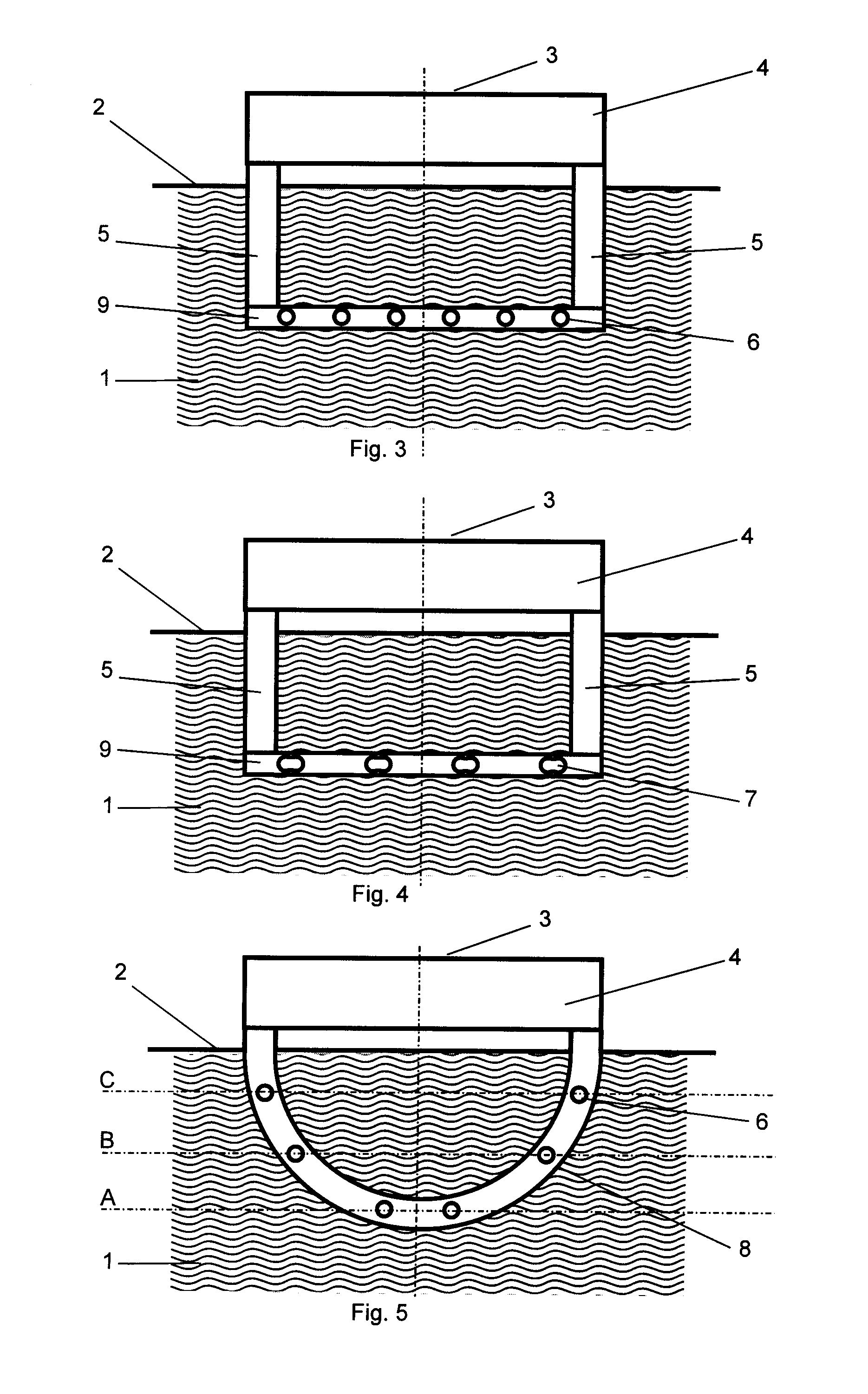
[0054]FIG. 3 shows the principal illustration of the configuration of a laying device (3) with two vertical blades (5) and...


PUM


Abstract

A laying device simultaneous lays at least two substantially parallel and axially spaced apart groups of flexible media lines in at least one flat layer in the soil, wherein each group of flexible media lines has at least one flexible media line. The laying device has a cutting device for generating at least one slot in the ground. The cutting device has one or more substantially vertical blades and a substantially horizontal blade connected to a lower end of the one or more vertical blades, or the cutting device, viewed in the cutting direction, has a round, semi-circular, oval, polygonal or Y-shaped configuration. At least two devices for dispensing the groups of media lines are arranged on the side of the laying device that is facing away from the cutting direction.

Description

BACKGROUND OF THE INVENTION[0001]Subject matter of the present invention is a laying device that makes it possible to lay simultaneously at least two groups of flexible media lines in a surface-near area axially horizontally spaced apart and parallel to one another, wherein the laying device comprises a cutting device for generating a slot in the ground and the cutting device is moved through the ground wherein, viewed in the movement direction, devices for dispensing the groups of flexible media lines are arranged behind the cutting device.[0002]The prior art discloses several laying devices. For example, usually slots are generated in the ground and at the bottom thereof one or several cables or media lines are laid. Corresponding solutions are disclosed, for example, in DE 42 10 858 C2 or DE 199 28 683 C2. Known are also solutions in which a pipe is introduced into a slot that has been generated by means of a blade wherein at the same time also a warning band and a control line a...

Claims


Application Information

Patent Timeline
Patent Type & Authority Applications(United States)
IPC IPC(8): F16L1/028H02G1/06
CPCE02F5/101H02G9/02H02G1/06E02F5/103
Inventor KLUGE, JENS
Owner DRESDEN UNIVERSITY OF TECHNOLOGY
Why Eureka
Try Eureka