Pipeline guide assemblies

a technology of pipeline guide and assembly, which is applied in the direction of pipe-laying vessels, pipe/joints/fittings, pipe-laying and repair, etc., can solve the problems of increasing difficulty in handling, limited length of lower ramp, and heavy weight of lower guide arrangement 61, so as to reduce the load on the vessel

Inactive Publication Date: 2011-04-07
HEEREMA MARINE CONTRACTORS NEDERLAND SE
View PDF8 Cites 12 Cited by
  • Summary
  • Abstract
  • Description
  • Claims
  • Application Information

AI Technical Summary

Benefits of technology

[0090]In a suitable embodiment, during the laying of the pipeline a central longitudinal plane of the pipeline laying vessel is oriented at an angle to the direction of the pipeline trajec

Problems solved by technology

One disadvantage is that the lower guide arrangement 61 is very heavy and becomes progressively heavier towards the lower end.
Due the trumpet shape, the length of the lower ramp is also limited, because the increasing weight limits the length, and the increasing diameter at the lower end makes handling increasingly difficult.
The adjustable roller boxes of U.S. Pat. No. 6,524,030 are large and heavy, especially when they have to suit large diameter ranges, whic

Method used


Image

  • Pipeline guide assemblies
  • Pipeline guide assemblies
  • Pipeline guide assemblies

Examples


Embodiment Construction

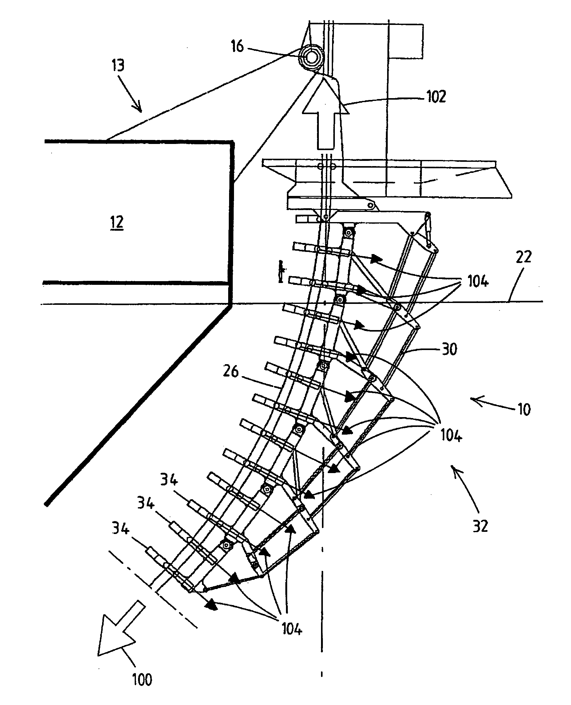
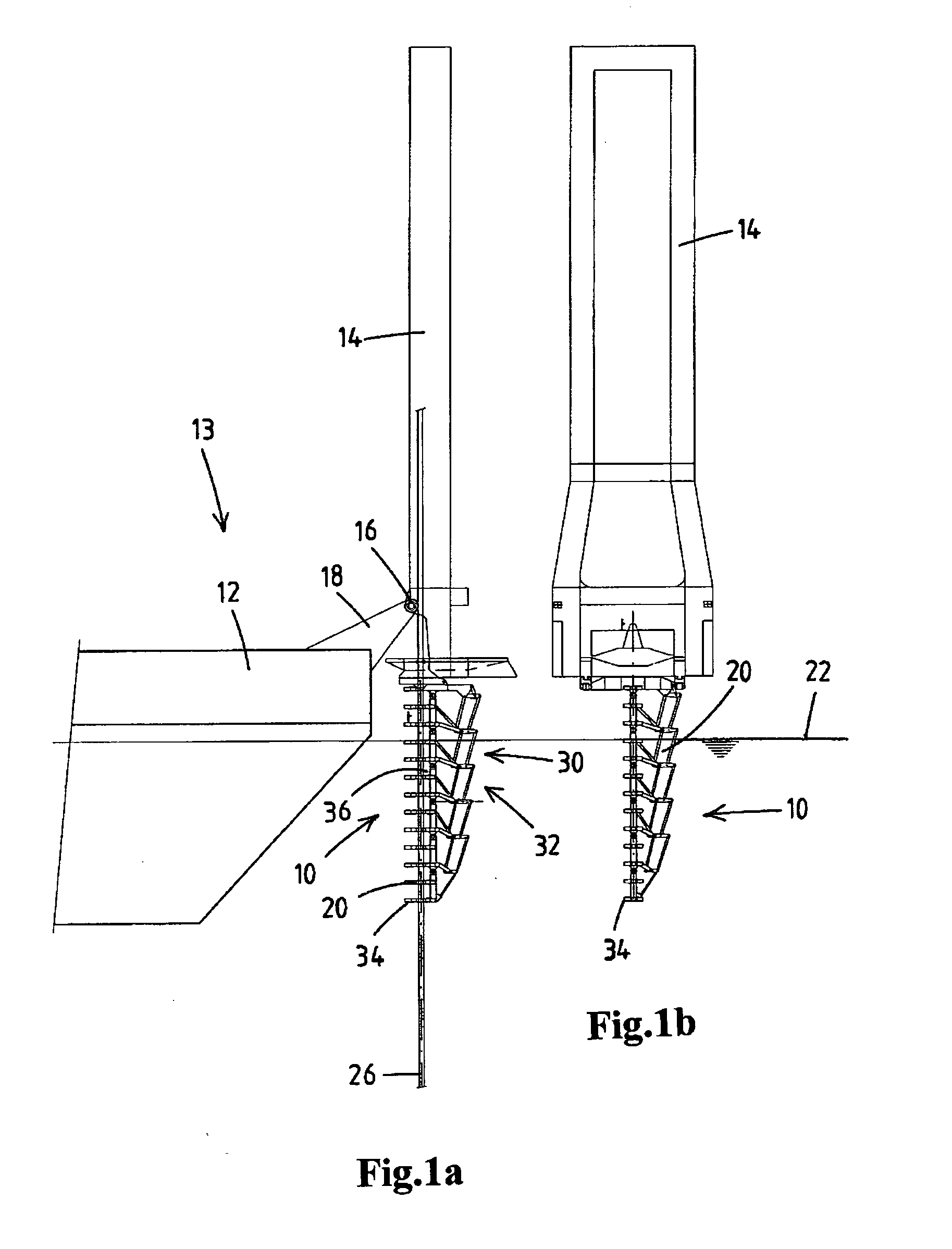
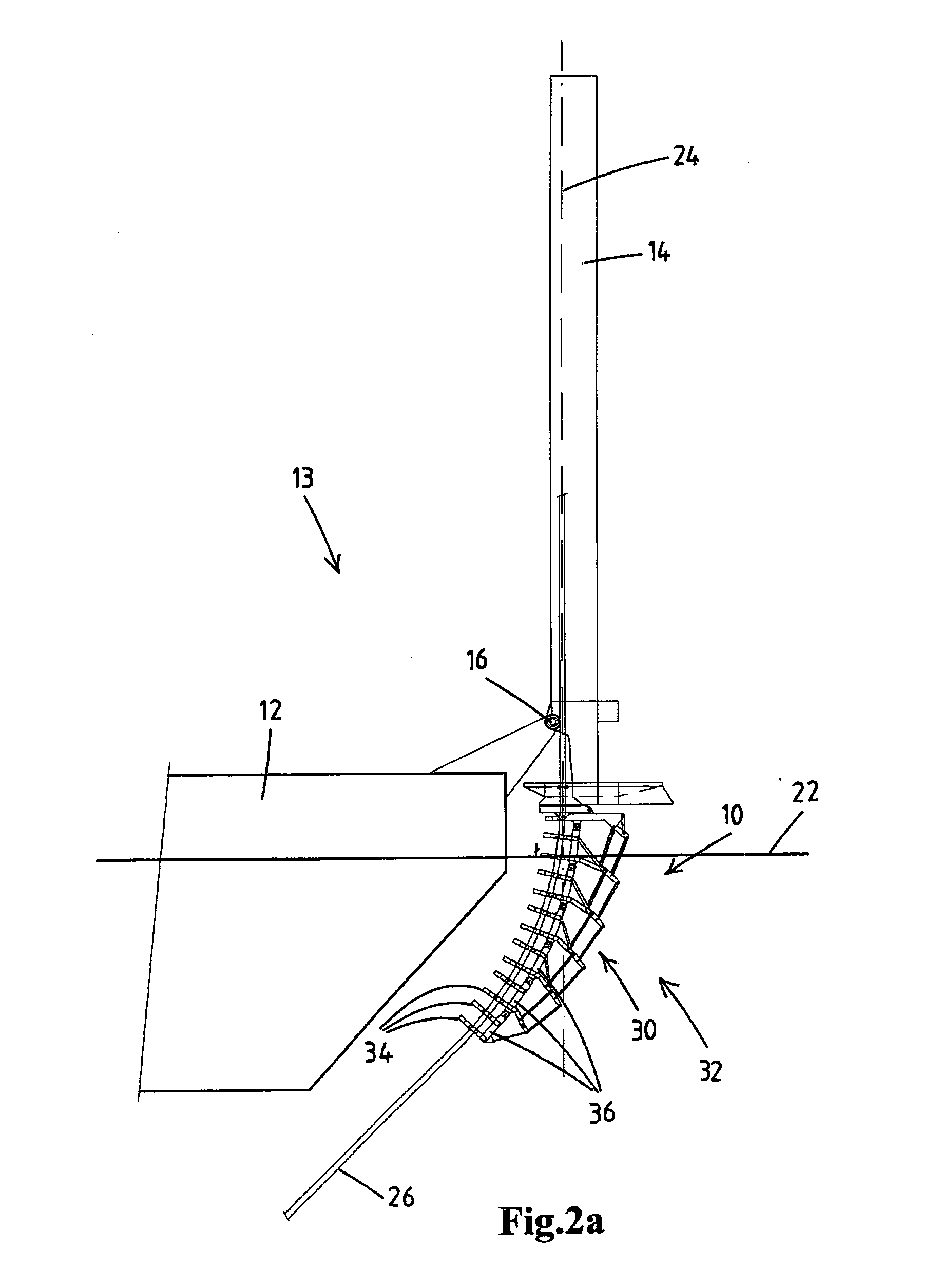
[0114]Turning to FIGS. 1a, 1b, 2a, 2b, 3 and 4, a pipeline guide assembly 10 according to the invention is shown. The pipeline guide assembly 10 is mounted to a J-lay tower 14 which is connected to the hull 12 of the vessel 13. The J-lay tower may be mounted to the rear end or the forward end of the vessel, or to the side of the vessel. The J-lay tower may also be positioned above a moonpool or in a slot or recess in the hull of the vessel 12. It is also possible that the pipeline guide assembly 10 is connected directly to the hull 12 of the vessel 13, instead of via the J-lay tower 14.

[0115]The J-lay tower 14 and the pipeline guide assembly 10 define a firing line 24, along which a pipeline 26 (or pipe string) is launched from the vessel 13.

[0116]In the shown embodiment, the J-lay tower 14 is connected to the hull 12 via a hinge 16 and an arm 18. The J-lay tower may be of any design known in the field of the art.

[0117]The pipeline guide assembly 10 may also be used in S-lay, V-lay,...


PUM


Abstract

The present invention relates to a pipeline guide assembly for a pipeline laying vessel, the pipeline guide assembly comprising:—a plurality of segments (20) pivotably interconnected via hinges (38) in an end-to-end relationship, each segment comprising at least one pipeline support (34) constructed to support a pipeline, wherein the pipeline supports provide a firing line (24) along which a pipeline can be launched,—a curvature mechanism (32) comprising at least one actuator (68, 68a, 68b, 68c, 68d), the curvature mechanism constructed for pivoting each segment relative to the next segment such that in use the segments provide a curved firing line, wherein the pipeline supports limit the curvature of the pipeline as it is launched along said curved firing line. The present invention also relates to a vessel comprising the stinger. The present invention also relates to a method of laying a pipeline utilizing the stinger of the invention.

Description

CROSS-REFERENCE TO RELATED APPLICATIONS[0001]This application is the National Stage of International Application No. PCT / NL2008 / 000143, filed Jun. 3, 2008, the contents of which is incorporated by reference herein.FIELD OF THE INVENTION[0002]The present invention relates to a pipeline guide assembly for a pipeline laying vessel. The present invention further relates to a pipeline laying vessel comprising such a pipeline guide assembly and to a method of laying a pipeline which uses the pipeline guide assembly.BACKGROUND OF THE INVENTION[0003]Such a pipeline guide assembly is often referred to as a “stinger”.[0004]In the field of the art, pipeline laying vessels are provided which are based on J-lay, S-lay, or reel-lay. These pipelaying methods are widely known. Some other variants are also used.[0005]In these known methods, a pipeline is laid by the vessel. As the vessel moves forward, the pipeline is launched from the vessel and lowered to the seabed. Many publications are known in...

Claims


Application Information

Patent Timeline
IPC IPC(8): F16L1/12B63B35/03
CPCB63B35/03F16L1/235F16L1/225F16L1/19
Inventor VAN GRIEKEN, GERARDUS CORNELIUSHILLENAAR, MAIKEL
Owner HEEREMA MARINE CONTRACTORS NEDERLAND SE
Why Eureka
Try Eureka