Optimizing the efficiency and energy usage of a geothermal multiple heat pump system

a geothermal multiple heat pump and efficiency optimization technology, applied in heat pumps, lighting and heating apparatus, heating types, etc., can solve the problems of inefficient operation of geothermal loop, low flow rate through plastic piping usually used, and multiple heat pump systems providing no means of reducing electrical demand, so as to optimize the efficiency of the overall system and optimize the coefficient of performance

Inactive Publication Date: 2011-05-19
SIEGENTHALER JOHN
View PDF3 Cites 38 Cited by
  • Summary
  • Abstract
  • Description
  • Claims
  • Application Information

AI Technical Summary

Benefits of technology

The present invention broadly provides an operating geothermal heat pump system that allows the operator to optimize the efficiency of the overall system by allowing variation of the earth loop flow rate depending upon the load requirements of, e.g., a single variable heat pump system or a multiple heat pump load loop, while optimizing circulator speed control in a multiple geothermal heat pump system. The system controlled in accordance with this invention avoids any problems that may be caused by slowing the circulators so that laminar flow results in the geothermal, or earth loop. The present invention comprises a system, and a method of operating the system, that allows for the optimization of the Coefficient of Performance of the system by permitting continuous variation of the earth loop flow rate as needed to balance the load requirement from the heat pump loop side of the system. Furthermore, where the flow rates for each of the two loops can be varied independently of each other as conditions change, i.e., where there are separate circulators for each of the earth loop and the heat pump loop. This invention provides a system that avoids any problem that may arise from low instantaneous heat transfer rate during laminar flow in the earth loop.
The method of this invention is represented by algorithms programmed into the data controller. The method of this invention provides for balancing the instantaneous heat exchange rate between the two loops by varying the speed of the ground loop circulator in response to changes in the required instantaneous heat exchange rate for the load loop so as to control the fluid flow rates of the ground loop in order to optimize the overall efficiency; by modifying the energy usages of the two loops so as to reduce the total energy usage, overall efficiency is improved.

Problems solved by technology

At times of low heat pump operation, the operation of the geothermal loop was inefficient in the sense that unnecessary energy was being expended in maintaining constant flow through the geothermal loop.
The prior art believed either that it was necessary to maintain a high flow through the ground loop in order to maintain turbulent flow; although some workers believed that the primary limiting parameter for geothermal heat flow was the low heat transfer rate through the plastic piping usually used.
Therefore, existing geothermal multiple heat pump systems provide no means of reducing the electrical demand of the earth loop circulator when a multiple heat pump array is operating at less than full capacity.

Method used


Image

  • Optimizing the efficiency and energy usage of a geothermal multiple heat pump system
  • Optimizing the efficiency and energy usage of a geothermal multiple heat pump system
  • Optimizing the efficiency and energy usage of a geothermal multiple heat pump system

Examples


Embodiment Construction

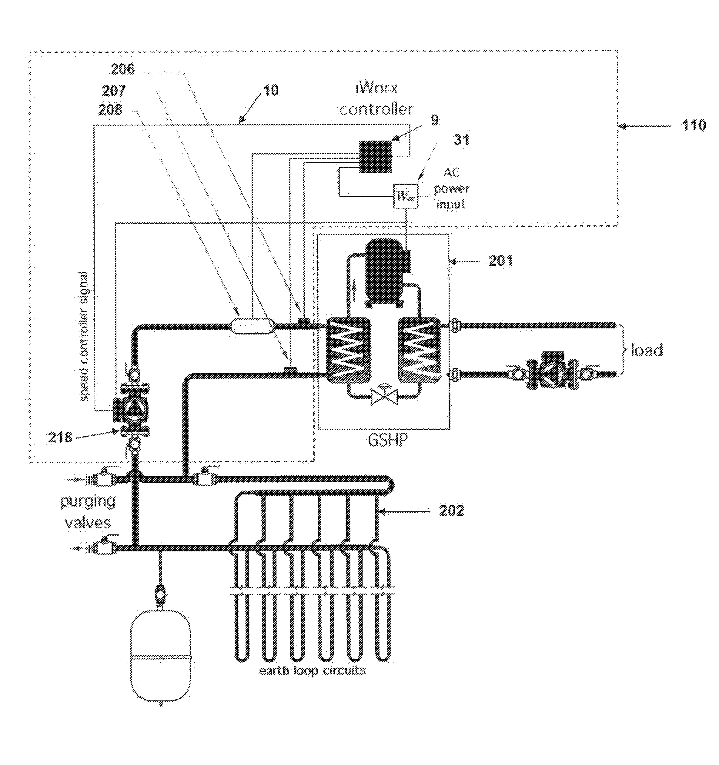
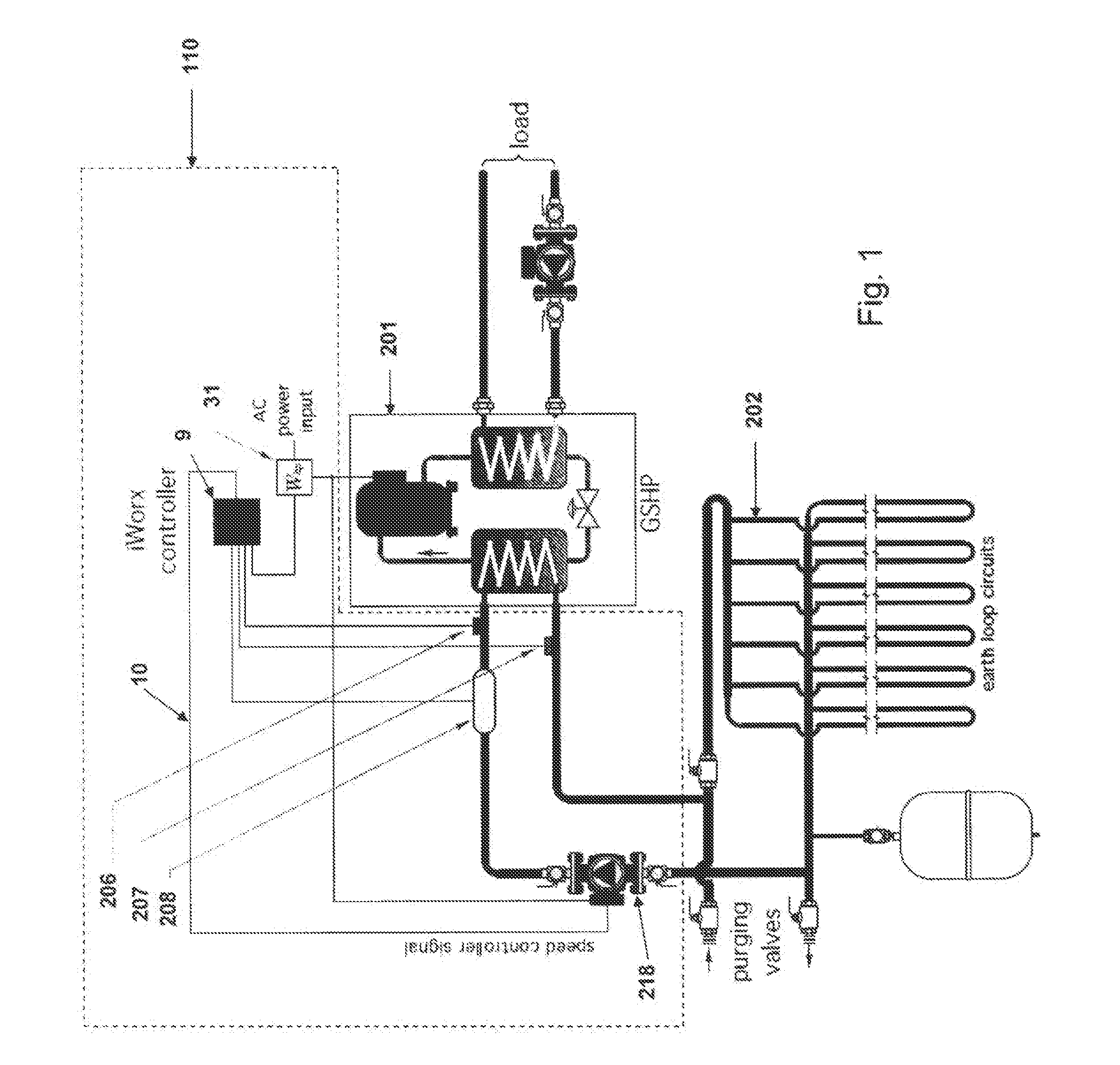
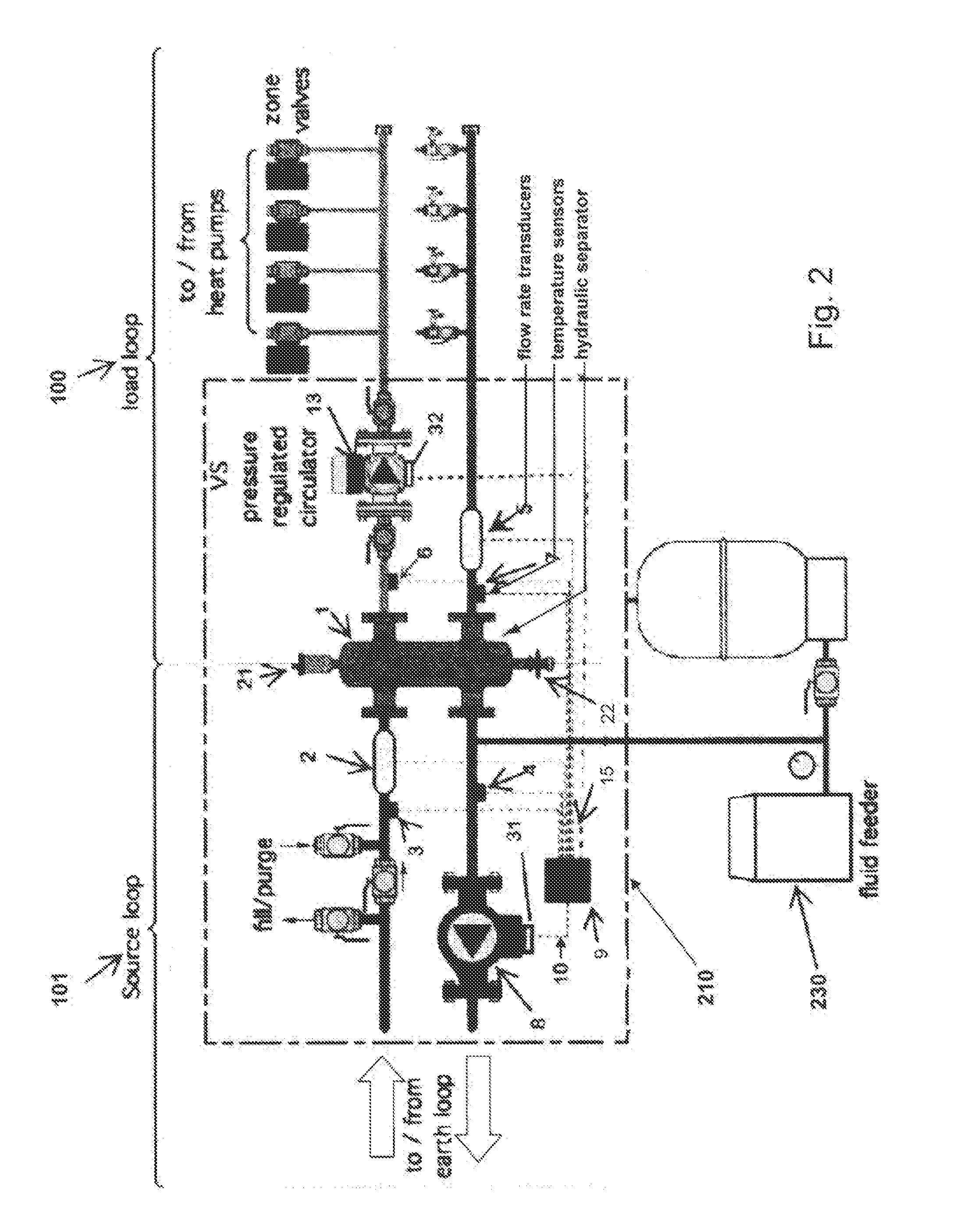
The operation of systems of this invention, in accordance with the general depictions of FIGS. 1 and 2, is preferably carried out using a digital controller 9, programmed in accordance with the algorithms represented by the flow charts of FIGS. 6 and 7, respectively. The program comprises a series of mathematical equations that are used to calculate the various parameters of the system, based upon data received by the controller 9 from the several sensors, and pre-entered information, such as the known properties of the circulating fluid, e.g., its specific heat and density. The data received provide the bases for controlling the earth loop circulator 8, by optimizing the flow through the earth loop 101, which tends to enhance the coefficient of performance (COP) of the overall system, and to maintain the instantaneous rate of heat transfer (Qearthloop) on the earth, or Source, loop side 101 of the hydraulic separator 1, at a value not less than the heat transfer (Qoutput) for the l...


PUM


Abstract

A system and a method for operating the system is provided to optimize heat exchange between a geothermal loop and a heat pump load loop for heating and cooling a structure. In the method, the flow rate through the earth loop is adjusted based on current thermal demand of a heat pump array, so as to reduce the electrical demand of the earth loop circulator when thermal demand from the heat pump loop is low. The method adjusts the speed of the earthloop circulator as required for the operating conditions of the heat pumps and earth loop, thereby permitting efficient laminar flow whenever possible, as long as thermal demand is met.The system of this invention provides a compact module containing a suitable digital data receiver and controller programmed to receive temperature and flow data and to calculate the needed flow in each loop to meet the thermal demand of the heat pump or pumps, and to signal the earthloop pump, and optionally a load loop pump, to operate at the necessary flow speed. Specifically, if flow in the earth loop transitions from turbulent to laminar, this method insures that the current thermal demand of the heat pumps is met, and if not, increasing the earth loop circulator speed to deliver the current thermal demand of the heat pumps.

Description

BACKGROUND OF THE INVENTIONIt is well-known to provide geothermal sources for systems of heat pumps for the heating or cooling of residential, commercial or industrial buildings. It has generally been assumed that the ground loop circulation remains constant even when used with multiple heat pump systems, where there can be widely varying energy requirements depending upon the number of heat pumps operating at any given time. For example, many office buildings are substantially empty overnight, so that the heat pumps maintained in operation during that period may vary by as much as a factor of 5, or more, as compared to the heat pumps operated during a business day. At times of low heat pump operation, the operation of the geothermal loop was inefficient in the sense that unnecessary energy was being expended in maintaining constant flow through the geothermal loop. The prior art believed either that it was necessary to maintain a high flow through the ground loop in order to mainta...

Claims


Application Information

Patent Timeline
Patent Type & Authority Applications(United States)
IPC IPC(8): F24J3/08
CPCF24J3/081F24J2003/089F25B30/06Y02E10/12F25B2600/13F25B2700/13Y02B30/745F25B2500/19F24D11/004F24T10/00F24T10/10F24T2010/56Y02B30/70Y02E10/10F28F27/00
Inventor SIEGENTHALER, JOHN
Owner SIEGENTHALER JOHN
Why Eureka
Try Eureka