

Electrical bond connection system
- Summary
- Abstract
- Description
- Claims
- Application Information
AI Technical Summary
Benefits of technology
Problems solved by technology
Method used
Image

Examples
Embodiment Construction
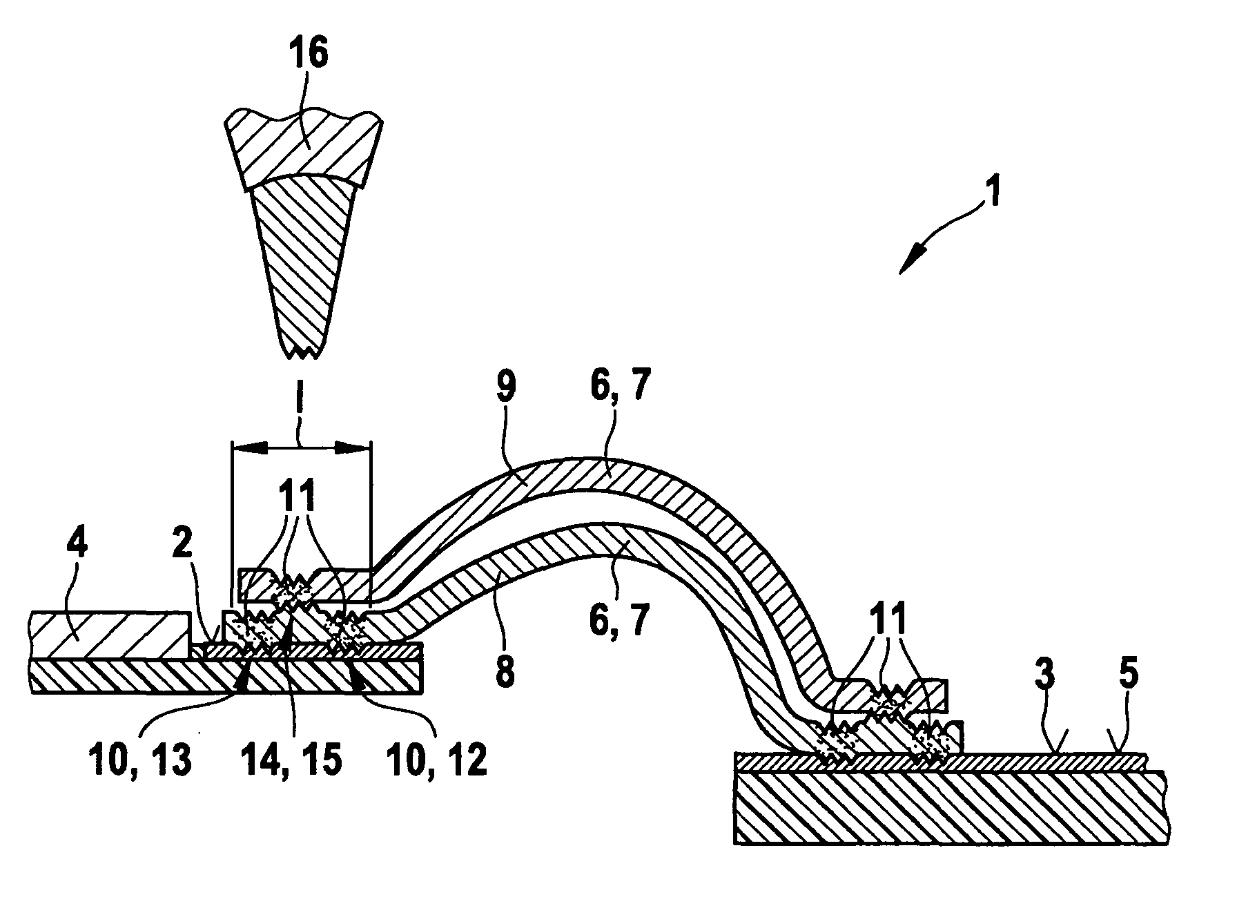
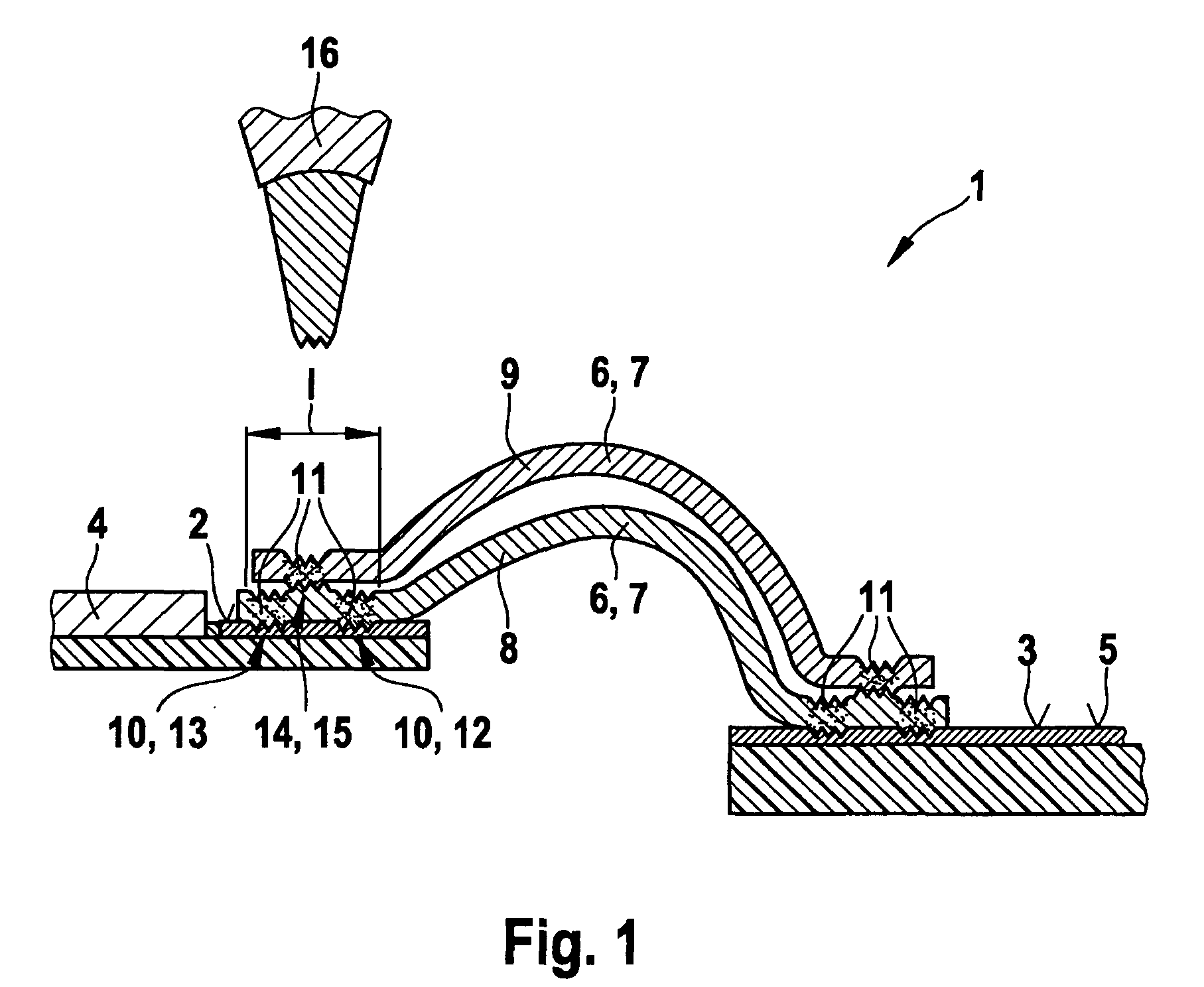
[0008]In one specific embodiment of the present invention, at least one of the conductors is designed as a ribbon bond. Ribbon bonds are known in the related art; such ribbon bonds, which do not have a square cross section, as is customary in the related art, but instead have an essentially rectangular cross section, are preferred here. This offers advantages from the point of view of process technology in the course of the bonding method because the bond connection is manufacturable more easily and more reliably if there is a smaller cross-sectional area in the vertical extent between the bonding tool and the contact surface.
[0009]In a preferred specific embodiment, at least one of the bond connections is a flat or linear bond connection. The bond connection between the conductor and the contact surface is consequently designed as a flat or of linear shape.
[0010]The bond connections are preferably present in particular on the ribbon bonds as contact strips running crosswise to the ...
PUM
| Property | Measurement | Unit |
|---|---|---|
| Bond | aaaaa | aaaaa |
Abstract
Description
Claims
Application Information