Inverted Vacuum Belt Conveyor System

Active Publication Date: 2016-04-07
SHERWOOD BERNARD J
View PDF15 Cites 4 Cited by
  • Summary
  • Abstract
  • Description
  • Claims
  • Application Information

AI Technical Summary

Benefits of technology

[0016]My previous patents, above, used a hollow extruded aluminium for combined conveyor support and air passages. This inverted version has two right angle mounting rails fastened to the upper side of a solid main frame with its associated machined chamber for the vacuum rail. The belt drive and tightening assemblies used in my previous patents above as well as the associated conveyor attaching and levelling hardware are secured to the rails where desired for the application. The space between these mounting rails is used to contain the air supply and exhaust retaining tubing as well as the vacuum generators and their electrical air supply control valves. These valves are turned on or off by electronic parts sensing units with high current carrying capabilities. These are now capable of operating the air control valve directly without having to go back and forth to a computer controller saving both the reaction time and wiring time and material. Said sensing unit can be mounted externally as convenient to detect parts present or not, efficiently turning vacuum on or off, section by section, as the part progresses along the conveyor. To cut down reaction time and compressed air consumption, the control valve and vacuum generator are secured between the mounting rails as close to each associated vacuum rail section supply hole as possible.
[0017]As in my previous patents above, in operation, any respective section of the vacuum rail only comes into operation when the

Problems solved by technology

Thusly, a vacuum seal is maintained between the load on the belt and the vacuum rail even as the belt flexes as loading is applied or released with the resulting belt dis

Method used


Image

  • Inverted Vacuum Belt Conveyor System
  • Inverted Vacuum Belt Conveyor System
  • Inverted Vacuum Belt Conveyor System

Examples


Example

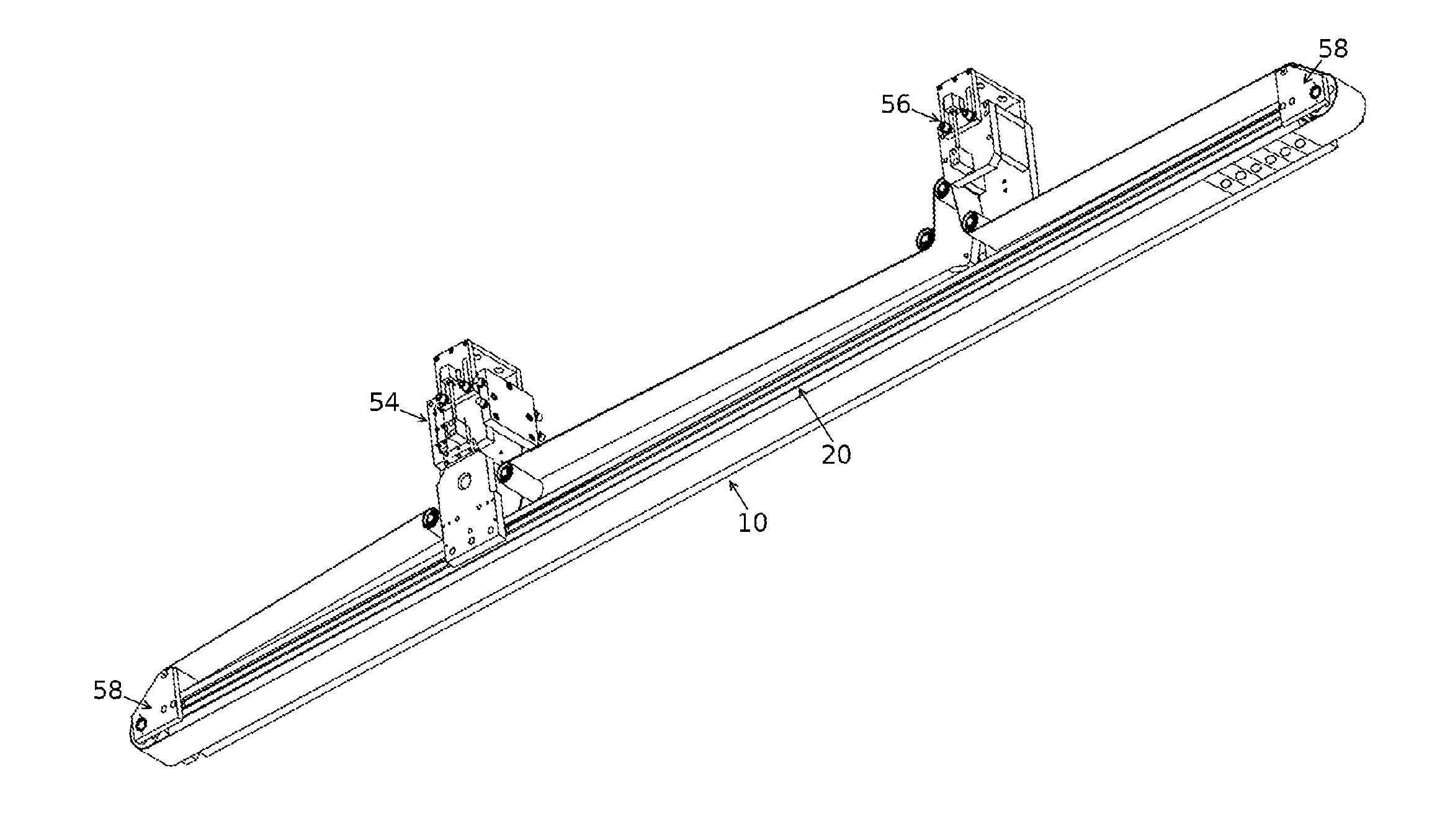
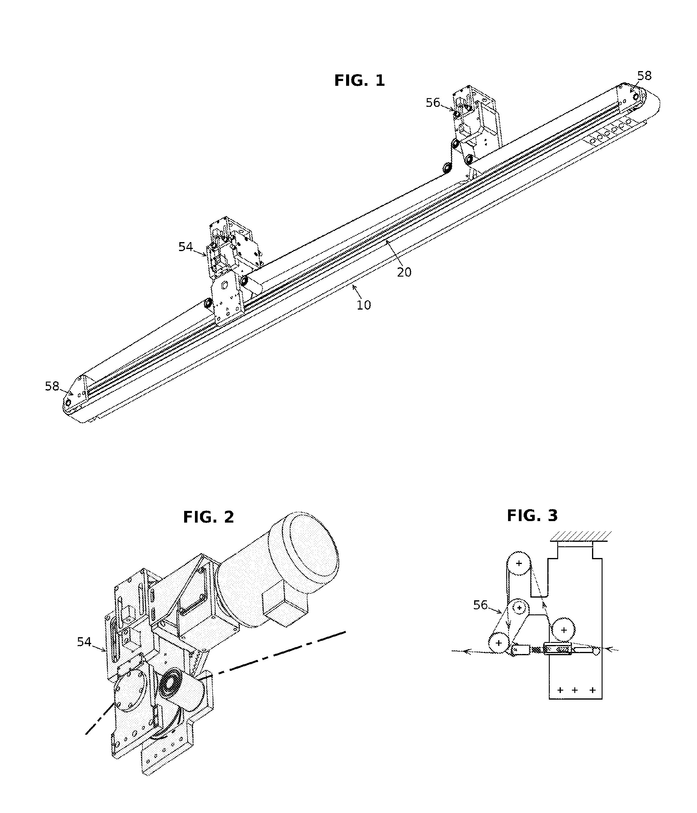
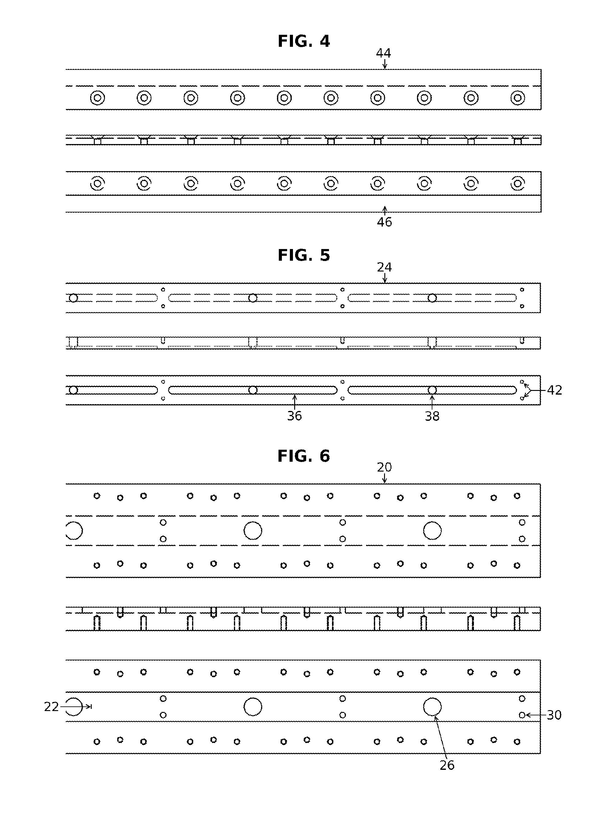
[0030]Referring to FIG. 1, the conveyor, 10 has a solid main frame as shown in FIGS. 6, 7 and 8 item 20. This frame has a longitudinal chamber (see FIGS. 6, 7&8), 22 machined into its lower surface to accept the vacuum rail FIGS. 5 & 8 item 24. Further to FIGS. 6, 7&8, 26 is a clearance hole to allow vacuum from the vacuum generator FIG. 7, 28 to be tubed (see FIGS. 7 & 8, 28′) to the vacuum rail and thus to the smooth surface of the toothed belt and so through the holes to the vacuum cup securing the load below the belt. FIGS. 6 & 8, 30 is a clearance hole for a shoulder bolt to allow movement up and down of the vacuum rail while maintaining it in the main frame chamber in FIGS. 6, 7&8, 22. FIG. 8, 32 are springs surrounding the shoulder bolts exerting a downward pressure between the main frame and vacuum rail creating a superior seal on the smooth upper surface of the belt FIG. 8, 34. FIG. 5, 24 is a vacuum rail being machined in identical sections to allow vacuum to be applied as...


PUM


Abstract

This invention is a vacuum belt conveyor designed to operate inverted and move articles suspended from its lower side rather than laying on top. This is achieved by the use of a matching toothed drive roller and toothed belt having its teeth facing outward and pierced between strategic teeth with vacuum cups secured through the holes. Vacuum is applied when needed to sections of a vacuum rail spring loaded against the smooth inner surface of the belt, the rail having a machined vacuum groove in horizontal alignment with the holes in the belt to provide vacuum to the cups. The belt and suspended articles secured to it by suction are held to the main frame by two retaining rails having clearance allowing passage of the cups.

Description

CROSS-REFERENCE TO RELATED APPLICATIONS[0001]N.A. (Not Applicable)STATEMENT REGARDING FEDERALLY SPONSORED RESEARCH OR DEVELOPMENT[0002]N.A.REFERENCE TO A SEQUENCE LISTING, A TABLE, OR A COMPUTER PROGRAM LISTING[0003]N.A.COMPACT DISC APPENDIX[0004]N.A.BACKGROUND OF THE INVENTION[0005]1. This invention is directed to an inverted conveyor system and in particular to an improved system incorporating a toothed vacuum belt for effecting the pneumatic transfer of articles while suspended from the lower side of the conveyor as opposed to lying on top.[0006]2. The use of pneumatic transfer with conveyor systems is well known and widely practiced both in regard to belt conveyors and agricultural purposes such as blowing or sucking grain, fertilizers, etc. along pipes. In the case of belt conveyors with pneumatic transfer, many systems are characterized by the use of wide open suction chambers with associated unduly large air-mass displacement requirements in the form of generated vacuum or of...

Claims


Application Information

Patent Timeline
IPC IPC(8): B65G17/32B65G15/64B65G15/58
CPCB65G17/323B65G15/64B65G15/58B65G21/22B65G23/04
Inventor SHERWOOD, BERNARD J.
Owner SHERWOOD BERNARD J
Why Eureka
Try Eureka