Walker

a walker and caster technology, applied in the field of walker, can solve the problems of affecting the support of the walker intended to provide the user, affecting the stability of the caster, and affecting the direction of the user,

Inactive Publication Date: 2011-06-23
PFAFFLIN ELLEN S
View PDF13 Cites 13 Cited by
  • Summary
  • Abstract
  • Description
  • Claims
  • Application Information

AI Technical Summary

Benefits of technology

[0008]The above recited object of the invention and other objects which will become apparent upon a reading of the following specification and claims are achieved by a walker in which the front legs are supported by wheels which track forwardly in conventional fashion. According to the invention, the wheels also each have a series of small diameter rollers mounted about the periphery thereof which rollers freely rotate about a tangential axis. The rollers at the bottom of the wheels in contact with the floor allow friction free sideways movement of the wheels. This enables turning of the walker without the need to exert a lifting force on the front legs so that the walker continues to maintain support for the user when making a turn. At the same time, forward tracking stability is largely maintained since the rollers can only rotate at right angles to the forward direction and thus any tendency to drift away from the forward direction is avoided as often happens with pivoted casters

Problems solved by technology

Thus, during turning movements, the support the walker intended to provide the user is compromised by the need to exert a lifting force on the walker.
While pivoted casters have been used to aid turning a walker, casters have a tendency to easily turn and have less than straight ahead directional stability.

Method used


Image

  • Walker
  • Walker

Examples


Embodiment Construction

[0011]In the following detailed description, certain specific terminology will be employed for the sake of clarity and a particular embodiment described in accordance with the requirements of 35 USC 112, but it is to be understood that the same is not intended to be limiting and should not be so construed inasmuch as the invention is capable of taking many forms and variations within the scope of the appended claims.

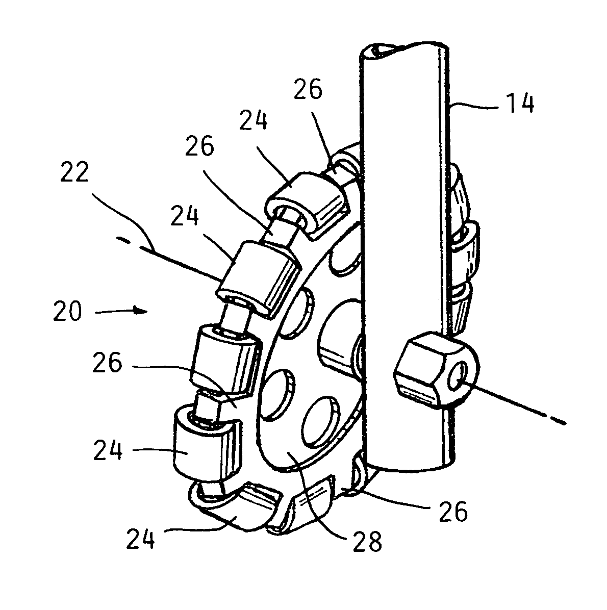
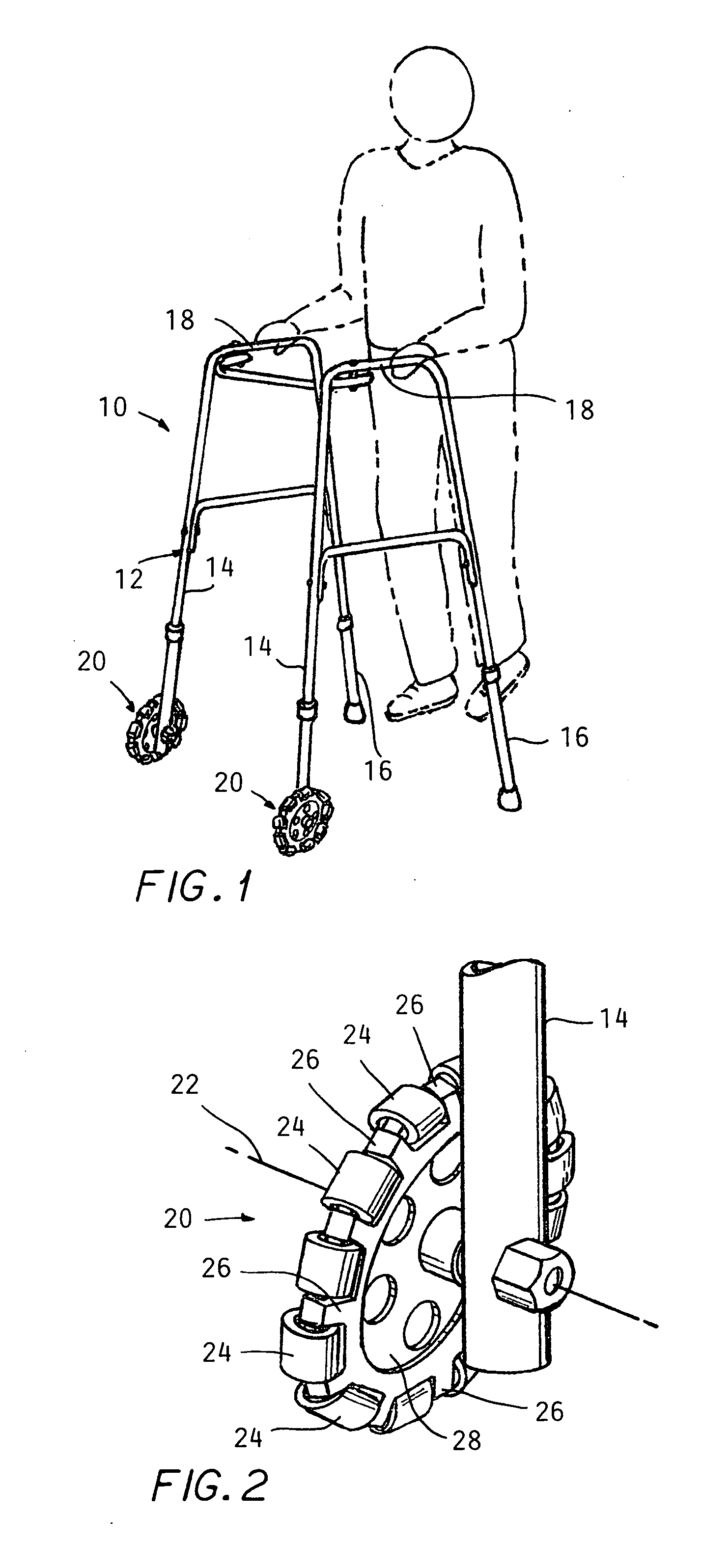
[0012]Referring to the drawings, a walker 10 according to the invention is shown which comprises a conventional framework 12, including two slightly forward angled front legs 14 and two slightly rearwardly angled rear legs 16, the legs supporting cross members 18 fixed thereto at the top positioned at a height conveniently graspable by the user. The legs 14, 16 may be made from tubular metal such as aluminum or steel and of a telescoping construction in the well known manner to allow length adjustments to be suited to the height of a particular user. The four angled legs...


PUM


Abstract

A walker has a wheel rotatably mounted to the lower end of each of a pair of front legs, each wheel having a series of end to end smaller diameter rollers mounted about the axis of wheels 10 define an outer perimeter of said wheels to allow easier turning of the walker without applying a lift force to the front legs while maintaining a tendency for the walker to track in a forward direction when a turning force is not applied.

Description

CROSS REFERENCE TO RELATED APPLICATIONS[0001]This application claims the benefit of U.S. provisional application No. 61 / 289,071, filed on Dec. 22, 2009.BACKGROUND OF THE INVENTION[0002]This application concerns walkers widely used to assist persons in walking if there is a risk of falling because of an injury, surgery or a debilitating illness or general feebleness produced as a result of advanced age.[0003]Such walkers comprise a stable four legged framework having horizontal members which the person holds on to for support as he or she walks forward, advancing the walker by pushing on the horizontal members.[0004]Typically, such walkers have wheels on the bottom of the front two legs to reduce resistance to pushing the walker forward, and rubber or other non-slip tips on the two rear legs to prevent the walker from having any tendency for uncontrolled forward rolling.[0005]When turning, a user exerts a lifting force on the front end of the walker to reduce the friction of the whee...

Claims


Application Information

Patent Timeline
Patent Type & Authority Applications(United States)
IPC IPC(8): A61H3/04B60B33/00
CPCA61H3/04B60B19/003B60B33/0039Y10T16/184B60B33/0063B60B2200/26B60B2360/32B60B33/0049
Inventor PFAFFLIN, ELLEN S.
Owner PFAFFLIN ELLEN S
Why Eureka
Try Eureka