Lift magnet mechanism for flywheel power storage systems

a technology of power storage system and magnet mechanism, which is applied in the direction of bearings, shafts and bearings, dynamo-electric machines, etc., can solve the problems of storage space, leakage and longevity, material restrictions and other factors inherent in the formation of magnetic arrays, etc., to relieve mechanical bearing wear, reduce storage space, and reduce power loss.

Inactive Publication Date: 2008-12-25
BEACON POWER LLC
View PDF17 Cites 12 Cited by
  • Summary
  • Abstract
  • Description
  • Claims
  • Application Information

AI Technical Summary

Benefits of technology

[0013]It is an additional objective of the instant invention to provide a flywheel power storage system possessing a motor / generator with minimal eddy current losses which displays use of mechanical bearings only as temporary backup as a rotor integral primary magnetically driven primary bearing system relieves wear on the mechanical bearings.
[0014]Further, as in any flywheel driven system, general objectives of this invention are to provide improved long-life flywheel batteries without sizable power losses, excessive internal heating, vacuum loss, extensive maintenance, explosion hazard and high cost.
[0015]It is an added objective of the instant invention to prevent the high speed rotor from becoming affixed to the stator due to extreme force and heat considerations experienced under any potential failure mode.
[0016]It is a further objective of the instant invention to enable the flywheel system to operate under cooler conditions and thus prevent inherent overheating and rotor and stator attachment, or sticking.
[0017]Another objective of the instant invention is to minimize the electrical power used in the lift magnet system, which inherently minimizes the heat generation, but additionally maintain proper control of the rotor.
[0018]Another objective of the instant invention is to provide an apparatus comprising a cylindrically shaped steel pole mechanism disposed to cover the segmented magnet array and thus during interface with any configuration of stator in order to minimize the eddy current and ambient heat. Thus use of said apparatus inherently minimizes stator winding heating, resulting thermal stresses, and possible outgassing of resin molding when such materials are utilized.

Problems solved by technology

As also illustrated in the above-referenced United States patents, such means as rechargeable electrochemical batteries offer some usages, but encounter huge problems involving key issues such as storage space, leakage and longevity.
However, as flywheel power storage system designs have evolved from smaller, physically limited structures with minimal storage capacity to the high capacity systems employing industrial sized magnetic members prevalent today, material restrictions and other such factors inherent with have arisen.
In modern applications, due to the need for extremely large magnetic arrays and magnetic members, current manufacturing capabilities restrict magnetic arrays to structures containing joined magnetic segments.
High sensitivity implies low magnetic force as the gap is large and excessively high force as the gap is small.
Lower force at the large gap requires designs with either stronger magnets or higher current to lift the rotor, and excessively high force at small gap would potentially damage the parts under the fault conditions.
Previous failure of high capacity flywheel systems often is found to be triggered by overloading and overheating of the touchdown ball bearing.
When utilizing a pure electromagnet lift magnet, failure offer occurs as the electrical power is tripped during normal operation due to the high lifting force requirement.
As the lifting force dissipates, the heavy rotor will then sit on the ball bearings, and thus, due to the heavy load, will heat up the ball bearings in a short expense of time.
Thus, as the ball bearing fails, the high speed rotor loses the mechanical support, and rotates basically out of round, contacting the casing.
Thus, wear, catastrophic at times and even explosions within the casing may occur.
High sensitivity implies that low magnetic force occurs when the gap is large in magnitude and excessively high force occurs when the gap is small in magnitude.
The larger gap condition at which lower force occurs requires designs with either stronger magnets or higher current to lift the rotor; whereas, on the other hand, the excessively high force at small gap could potentially damage parts or the overall system under fault conditions.

Method used


Image

  • Lift magnet mechanism for flywheel power storage systems
  • Lift magnet mechanism for flywheel power storage systems
  • Lift magnet mechanism for flywheel power storage systems

Examples


Embodiment Construction

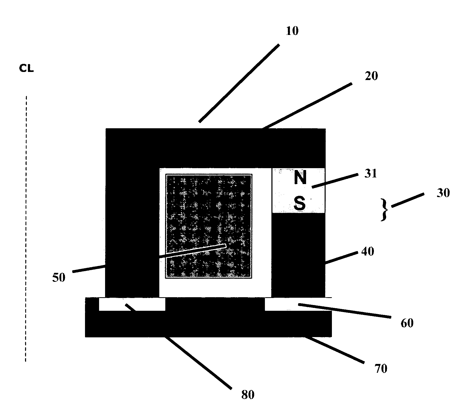
[0037]In flywheel driven power storage systems, the magnetic force generated either by permanent magnet or electromagnet or the combination of both is used to lift the rotor in a flywheel system. The magnetic force generated by a pair of stationary stator and rotor is normally highly sensitive to the air gap separating the stator and rotor. High sensitivity implies low magnetic force, as the gap is large and excessively high force as the gap is small.

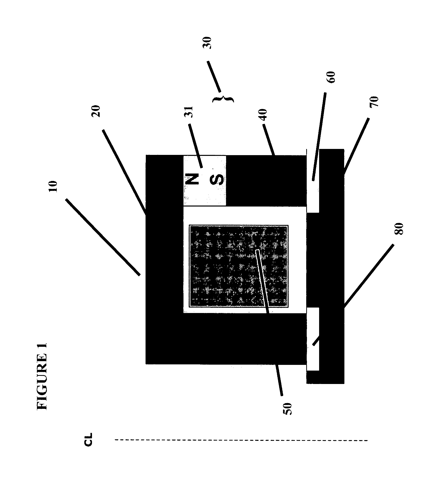
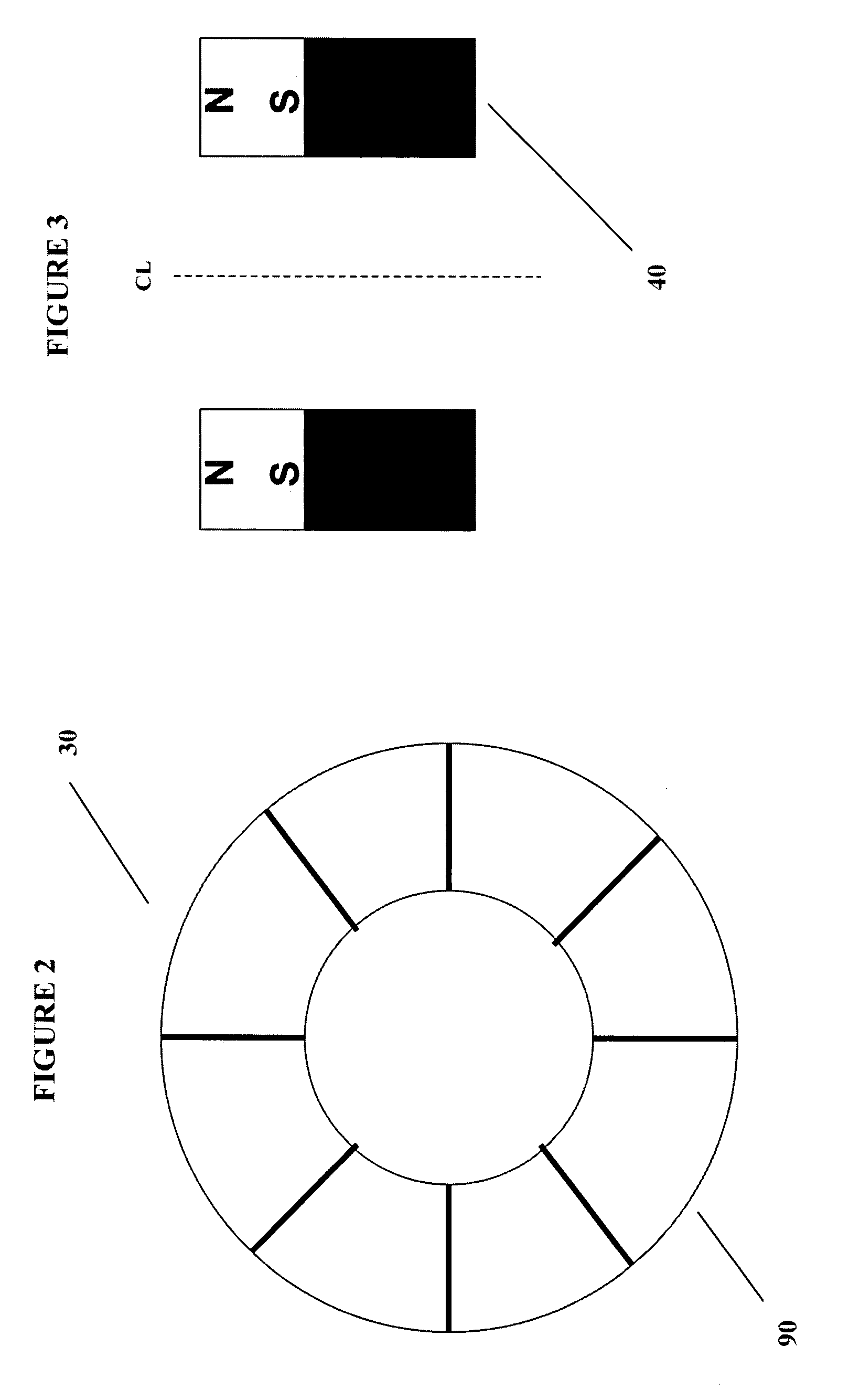
[0038]In order illustrate the numerous embodiments of the instant invention, referring first to FIG. 1 illustrates a simplified cutaway assembly block diagram of the flywheel power storage system magnetic ring apparatus 10 or magnetic lift portion of the instant flywheel battery, illustrating the stator housing and assembly 20, the permanent magnet array 30 which is comprised of segmented magnet array 31 and the steel cylindrical member 40 or pole 40, the coil 50, the gap between rotor and stator, or rotor / stator gap 60, and the rotor 7...


PUM


Abstract

Electric power is stored in a flywheel assembly, from a dc power buss, and supplied to the buss, through electronics associated with a motor/generator, its rotor integral with a flywheel supported by magnetic bearings. Upon operation, the flywheel assembly is released by mechanical backup bearings which then normally remain disengaged until shutdown as the flywheel assembly is levitated by the axial magnetic field. Enhancements developed herein smooth the flux density across discontinuities or segments present in permanent magnets due to presently limited capability for manufacture of large annular magnetic members. Herein, the introduction of a medium such as a steel cylindrical member to directly interface with the rotor as opposed to the segmented permanent magnet, greatly eradicates induced eddy current and heat on the rotor. In addition, exhibited is an annularly slotted rotor which allows for greater surface area for flux absorption.

Description

FIELD OF THE INVENTION[0001]The present invention relates generally to flywheel driven power storage systems and particularly to enhancements developed to smooth the flux density across discontinuities or segments present in permanent magnets due to present manufacturing capability.REFERENCES[0002]In general within the art, descriptions of flywheel driven power storage systems and their various related elements can be found in U.S. Pat. No. 5,614,777 set forth by Bitterly et al; U.S. Pat. Nos. 567,595, 5,708,312, 5,770,909, and 58,644,303 by Rosen et al; U.S. Pat. Nos. 3,860,300 and 4,147,396 by Lyman; U.S. Pat. Nos. 3,791,704 and 4,088,379 by Perper; U.S. Pat. No. 5,627,419 by Miller; U.S. Pat. No. 4,910,449 by Hiyama et al: U.S. Pat. No. 5,760,510 by Nomura et al: U.S. Pat. No. 5,777,414 by Conrad; U.S. Pat. No. 5,319,844 by Huang et al; U.S. Pat. No. 4,444,444 by Benedetti et al; U.S. Pat. No. 5,844,339 by Schroeder et al; U.S. Pat. Nos. 5,495,221, 5,783,885, 5,847,480, 5,861,690...

Claims


Application Information

Patent Timeline
Patent Type & Authority Applications(United States)
IPC IPC(8): H02K7/02H02K7/09
CPCF16C32/0459Y02E60/16H02K7/09H02K7/025F16C2361/55
Inventor WANG, JIMPO
Owner BEACON POWER LLC
Why Eureka
Try Eureka