Hybrid touchdown bearing system

a technology of hybrid bearings and bearings, which is applied in the direction of mechanical energy handling, mechanical apparatus, engine components, etc., can solve the problems of storage space, leakage and longevity, and failure of high-capacity flywheel systems, so as to relieve mechanical bearing wear, reduce power loss, and reduce the effect of eddy current loss

Inactive Publication Date: 2009-04-02
BEACON POWER LLC
View PDF7 Cites 8 Cited by
  • Summary
  • Abstract
  • Description
  • Claims
  • Application Information

AI Technical Summary

Benefits of technology

[0017]It is an additional objective of the instant invention to provide a flywheel power storage system possessing a motor / generator with minimal eddy current losses which displays use of mechanical bearings only as temporary backup as a rotor integral primary magnetically driven primary bearing system relieves wear on the mechanical bearings.
[0018]Further, as in any flywheel driven system, general objectives of this invention are to provide improved long-life flywheel batteries without sizable power losses, excessive internal heating, vacuum loss, extensive maintenance, explosion hazard and high cost.
[0019]It is an added objective of the instant invention to prevent the high speed rotor from becoming affixed to the stator due to extreme force and heat considerations experienced under any potential failure mode.
[0020]Another objective is to eliminate need for lubricants in mechanical backup bearings, to remove a cause of vacuum loss, frequent maintenance, and mechanical bearing failures. It is a further object of the instant invention to introduce a device which utilizes a combination of proven technologies, in order to achieve the above stated goals and thus operate at high loads and high speeds and resist overheating.
[0021]The instant hybrid touchdown bearing is a hybrid as the system provides static bearing weight support upon failure, but also allows the flywheel to continue rotation, thus continuing power generation and minimizing power loss.

Problems solved by technology

As also illustrated in the above-referenced United States patents, such means as rechargeable electrochemical batteries offer some usages, but encounter huge problems involving key issues such as storage space, leakage and longevity.
However, as flywheel power storage system designs have evolved from smaller, physically limited structures with minimal storage capacity, to the high capacity systems employing industrial sized magnetic members prevalent today, material restrictions and other such inherent factors have arisen.
In modern applications, due to the need for extremely large magnetic arrays and magnetic members, failure of high capacity flywheel systems can be triggered by overloading and overheating of the touchdown ball bearing.
When utilizing a pure electromagnet lift magnet, failure often occurs as the electrical power is tripped during normal operation due to the high lifting force requirement.
As the lifting force dissipates, the heavy rotor will then sit on the ball bearings, and thus, due to the heavy load, will heat up the ball bearings in a short expanse of time.
Thus, as the ball bearing fails, the high speed rotor loses the mechanical support, and rotates basically out of round, contacting the casing.
Thus, wear, catastrophic at times and even explosions within the casing may occur.
These systems can be prone to failure due to power outage or overheating and during this type of event, the entire weight of the rotor may crash down upon and subsequently rests upon a mechanical backup bearing.
Obviously, designing backup bearing systems to rectify these problems arising from power failure and / or overheating has become more challenging as flywheels become larger and operate at high speeds.
Various types of mechanical bearings have been considered, designed and tested, but the extreme loads involved invariably cause the bearing to overheat, resulting in a very short life cycle and catastrophic failure.

Method used


Image

  • Hybrid touchdown bearing system
  • Hybrid touchdown bearing system
  • Hybrid touchdown bearing system

Examples


Embodiment Construction

[0027]The detailed description set forth below in connection with the appended drawings is intended as a description of presently-preferred embodiments of the invention and does not represent the only forms in which the present invention may be constructed and / or utilized. The description sets forth the functions and the sequence of steps for constructing and operating the invention in connection with the illustrated embodiments. However, it is to be understood that the same or equivalent functions and sequences may be accomplished by different embodiments that are also intended to be encompassed within the spirit and scope of the invention, such as flywheel systems with magnetic bearings used in a variety of applications.

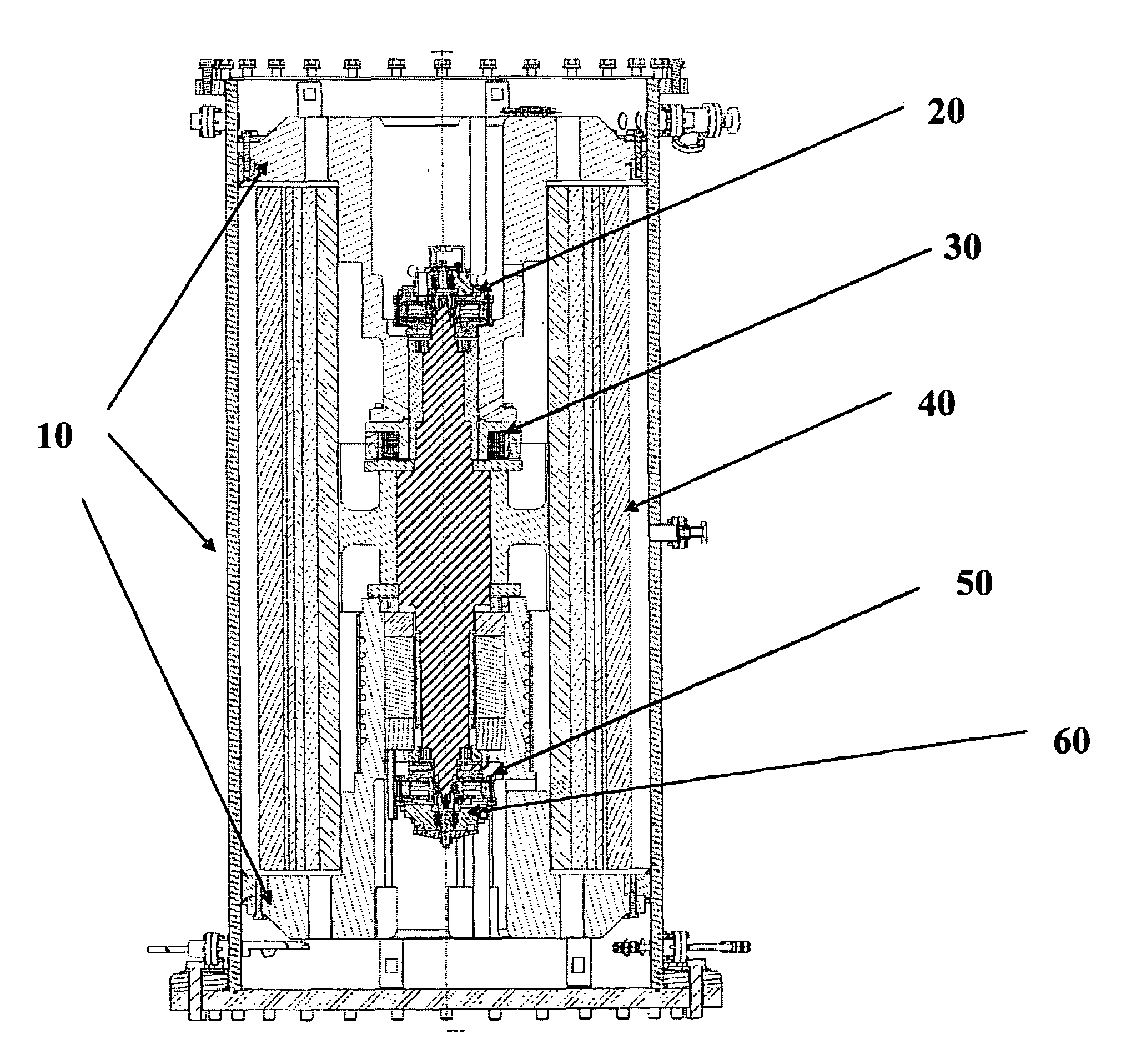
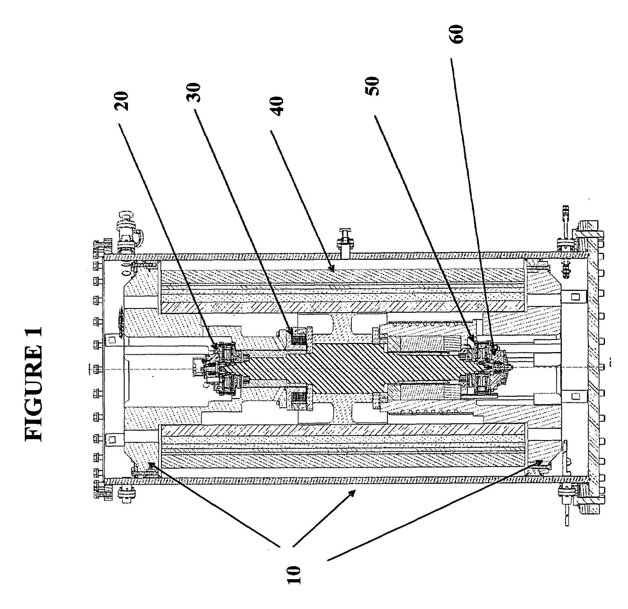
[0028]In flywheel driven power storage systems, as well as in many other applications which involve shafts and other implements rotating at high revolutions per minute, bearing overheating or power failure can create catastrophic damage to system components. In the...


PUM


Abstract

Upon operation, flywheel assemblies sand other such rotational mechanisms are released by mechanical backup bearings, which then normally remain disengaged until shutdown as the flywheel assembly is levitated by the axial magnetic field. However, either due to over heating of bearings, power failure or other stimuli, flywheels often suffer a phenomenon deemed as touchdown down from the levitation state. During this touchdown event, flywheels inherently lose rotational momentum, thus ceasing to generate and release power and often cause damage to components as well as casing. Enhancements developed herein, through the introduction of the instant secondary hybrid touchdown bearing system, allow flywheels and other such systems to retain rotational momentum and continue generation of energy. Further, the instant system negates damage to system components, as well as bearing wear.

Description

FIELD OF THE INVENTION[0001]The present invention relates generally to flywheel driven power storage systems and particularly to enhancements developed for bearings, secondary or back up bearing systems relied upon during failure modes in order to sustain less bearing wear and impact damage and evince stronger recovery from power loss.REFERENCES[0002]In general within the art, descriptions of flywheel driven power storage systems and their various related elements can be found in U.S. Pat. No. 5,614,777 set forth by Bitterly et al; U.S. Pat. Nos. 567,595, 5,708,312, 5,770,909, and 58,644,303 by Rosen et al; U.S. Pat. Nos. 3,860,300 and 4,147,396 by Lyman; U.S. Pat. Nos. 3,791,704 and 4,088,379 by Perper; U.S. Pat. No. 5,627,419 by Miller; U.S. Pat. No. 4,910,449 by Hiyama et al: U.S. Pat. No. 5,760,510 by Nomura et al: U.S. Pat. No. 5,777,414 by Conrad; U.S. Pat. No. 5,319,844 by Huang et al; U.S. Pat. No. 4,444,444 by Benedetti et al; U.S. Pat. No. 5,844,339 by Schroeder et al; U.S...

Claims


Application Information

Patent Timeline
Patent Type & Authority Applications(United States)
IPC IPC(8): H02K7/02H02K7/09F16C19/54F16C32/06
CPCF16C32/0442F16C39/02Y02E60/16H02K7/025H02K7/09H02K5/1732F16C2361/55F16C39/066
Inventor ARSENEAUX, JAMESWANG, JIMPO
Owner BEACON POWER LLC
Why Eureka
Try Eureka