Method and Apparatus for Data Communication Between a Base Station and a Transponder

a data communication and base station technology, applied in the field of methods and apparatus for data communication between a base station and a transponder, can solve the problems of inability to know the exact clock rate of the transponder, correspondingly difficult to distinguish the various symbols from one another, and the base station also does not know the resolution of the given transponder, so as to improve the flexibility and improve the duration of the data communication. , the effect of less error-prone duration

Inactive Publication Date: 2011-07-14
ATMEL CORP
View PDF15 Cites 4 Cited by
  • Summary
  • Abstract
  • Description
  • Claims
  • Application Information

AI Technical Summary

Benefits of technology

[0021]It is therefore an object of the present invention to provide an improved and more flexible data communication between base station and transponder. The data communications and / or the data communication system should also be adaptable to the greatest degree possible to the particular transponders in use. A further object of the present invention is to make the duration of a data communication less error-prone.

Problems solved by technology

The problem with this, however, is that the precise clock rate of the transponder is not known to the base station.
Furthermore, the base station also does not know what resolution a given transponder is working with.
This is especially serious for the demodulation and decoding by the transponder of the signals transmitted by the base station, since such transponders with a very low resolution are not capable of decoding with high reliability the symbols transmitted at a high data transmission rate by the base station, for example.
Especially at very high data transmission rates, such transponders, because of their low resolution, find it correspondingly difficult to distinguish the various symbols from one another, for example “0”, “1”, “EOT”.
Data communication with such inexpensive, “low cost” transponders is thus comparatively error-prone, particularly when the base station is informing such a transponder by means of the header section that a relatively high data transmission rate is desired, but the transponder does not support this rate because of its structure.

Method used


Image

  • Method and Apparatus for Data Communication Between a Base Station and a Transponder
  • Method and Apparatus for Data Communication Between a Base Station and a Transponder
  • Method and Apparatus for Data Communication Between a Base Station and a Transponder

Examples


Embodiment Construction

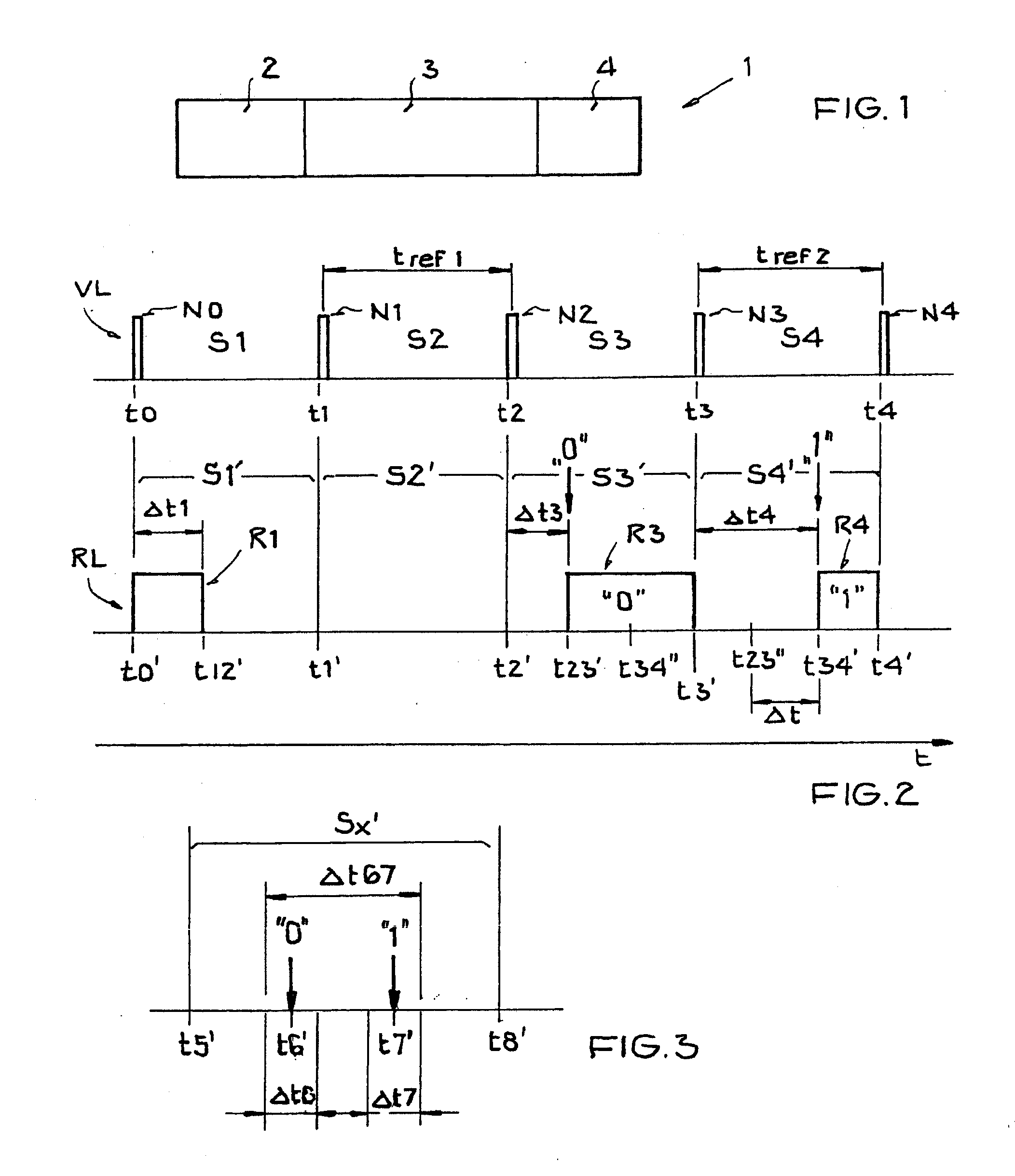
[0056]In the drawings, like or functionally like elements, data, and signals are identified with the same reference labels, unless otherwise specified. The representations in FIGS. 1-3 each relate to a time sequence of a specific data communication with respect to an information packet.

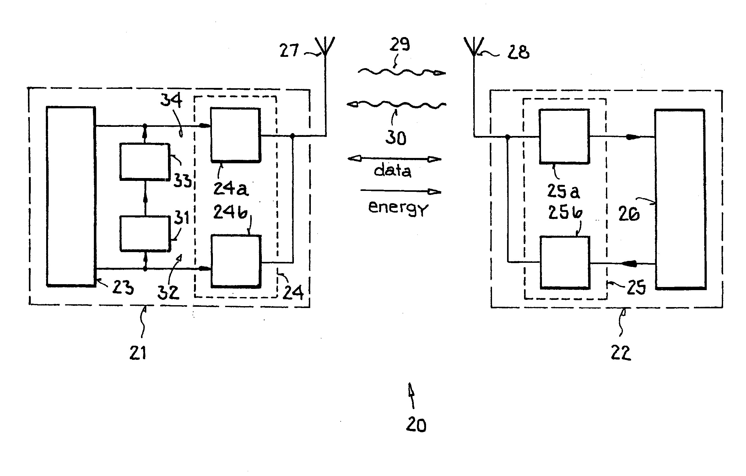
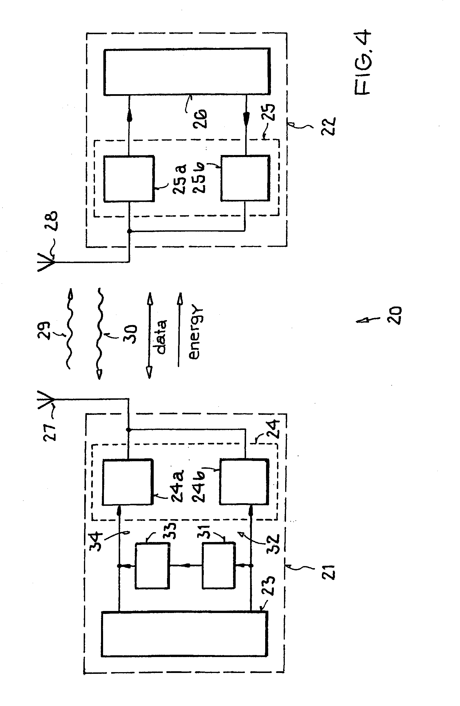
[0057]Data communication between a base station and a transponder defines a channel hereinafter referred to as the forward link VL (also sometimes called the downlink). Conversely, the data communication from the transponder back to the base station defines a channel that is generally referred to as the return link RL (also sometimes called the uplink). In addition to the data communication in the return link RL, in the case of transponders based on backscattering, there also takes place a data communication between the transponder and the base station in which a transmitted signal is scattered back to the transmitter using the backscatter cross-section of the receiver's antenna. This method is also g...


PUM


Abstract

A method and system for data communication between a base station and at least one transponder via a high-frequency electromagnetic carrier signal onto which information packets are modulated. Each information packet has a header section, a middle section, and a trailer section. The header section can be provided in a forward link of a data communication between the base station and the transponders for controlling data communication. The header section is used in a return link of a data communication in order to transmit information from the transponder to the base station.

Description

[0001]This nonprovisional application claims priority under 35 U.S.C. §119(a) on German Patent Application No. DE 102004018539.5, which was filed in Germany on Apr. 14, 2004, and which is herein incorporated by reference.BACKGROUND OF THE INVENTION[0002]1. Field of the Invention[0003]The present invention relates to a method for data communication between a base station and at least one transponder by, for example, a high-frequency electromagnetic carrier signal onto which information packets are modulated. Each information packet can have a header section, a middle section, and a trailer section. The header section can be provided in a forward link of a data communication between the base station and the transponders for controlling the data communication. The header section can be used in a return link of a data communication in order to transmit information from a transponder to the base station communicating with this transponder. The invention further relates to a base station ...

Claims


Application Information

Patent Timeline
Patent Type & Authority Applications(United States)
IPC IPC(8): H04W4/00G06K7/00G06K19/07G08C17/02H04L29/06
CPCG06K7/0008
Inventor FRIEDRICH, ULRICH
Owner ATMEL CORP
Why Eureka
Try Eureka