LED arrangement and LED driving method

a technology of led driver and led arrangement, which is applied in the direction of semiconductor devices for light sources, planar light sources, lighting and heating apparatus, etc., can solve the problem of limited retrofit applications of available space for led driver

Active Publication Date: 2019-08-06
SIGNIFY HLDG BV
View PDF9 Cites 0 Cited by
  • Summary
  • Abstract
  • Description
  • Claims
  • Application Information

AI Technical Summary

Benefits of technology

[0006]There is a need for a low-cost and compact driver architecture, such as a linear tapped driver, which does not suffer the drawbacks of a light output variation over area. It would be advantageous to provide a lighting structure that uses tapped linear driver but also has a uniform / even light output among different tapped groups throughout the overall light output surface such as the whole lamp.
[0018]This less turning on duration of the second group and the higher light emitting surface fraction of the second group could compensate with each other. In other words, the LEDs turned on for less duration is with a high light emitting surface fraction. Thus due to the human eye's perception delay, the same light comes out of the second area as that of the first area, and the whole light output surface emits the same light and is more uniform.
[0026]In this way, the different LED groups are made to emit light with roughly the same intensity per unit area, i.e. the same visible output brightness over area when averaged over time. The visible light is uniform throughout the light output surface, and the drawback of the tapped linear driver is compensated.
[0030]This provides a second way of differentiating the output density per unit area and in turn making the time-average intensity closer, by having more closely packed LEDs when those LEDs are turned on for a shorter time.
[0033]In this way, a larger current is used when more series LEDs are being driven. This matches the input current with the sine wave of the mains input voltage and reduces total harmonic distortion.

Problems solved by technology

The available space for an LED driver has limited many retrofit applications for LED lamps, such as a tubular LED lamp.
A problem with the use of a tapped linear driver is that different sets of LEDs are turned on at different times and for different duration, for example at different interval of a mains cycle.

Method used


Image

  • LED arrangement and LED driving method
  • LED arrangement and LED driving method
  • LED arrangement and LED driving method

Examples


Embodiment Construction

[0054]The invention provides an LED arrangement which uses a tapped driver driven by a rectified mains input. There are at least first and second groups of LEDs on a light output surface, which may be the tubular surface of a tubular LED lamp that provides the illumination. The second group of LEDs is bypassed when the input voltage is less than a certain threshold while the first group is still turned on. The total light output density for the LEDs of the second group (which are turned on for less of the mains cycle) per unit area of the light output surface is greater than the total light output density for the LEDs of the first group per unit area of the light output surface. This means the light output density per unit area when averaged over time is made more consistent between the two (or more) groups of LEDs.

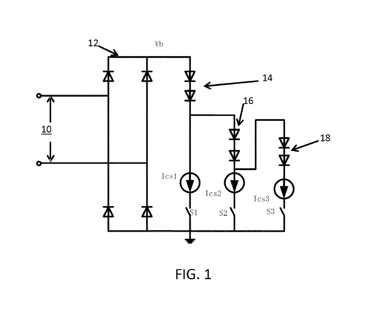
[0055]FIG. 1 shows a known tapped linear LED driver architecture which may be used to implement the LED arrangement of the invention.

[0056]The circuit of FIG. 1 comprises...


PUM


Abstract

An LED arrangement uses a tapped driver driven by a rectified mains input and placed over a light output surface. There are at least first and second groups of LEDs on the light output surface. The total light output density for the LEDs of the second group (which are turned on for less of the mains cycle) per unit area of the light output surface is greater than the total light output density for the LEDs of the first group per unit area of the light output surface. A fraction of a light emitting surface of the second group (16) of LEDs to a second area (20B) of the light output surface occupied in a macro view by the second group (16) of LEDs, is larger than a fraction of a light emitting surface of the first group (14) of LEDs to a first area (20A) of the light output sur face occupied in a macro view by the first group (14) of LEDs. This means the light output density when averaged over time is made more consistent between the two (or more) groups of LEDs.

Description

CROSS-REFERENCE TO PRIOR APPLICATIONS[0001]This application is the U.S. National Phase application under 35 U.S.C. § 371 of International Application No. PCT / EP2016 / 063038, filed on Jun. 8, 2016, which claims the benefit of International Application No. PCT / CN2015 / 081910, filed on Jun. 19, 2015 and European Patent Application No. 15192082.4, filed on Oct. 29, 2015. These applications are hereby incorporated by reference herein.FIELD OF THE INVENTION[0002]This invention relates to an LED arrangement and LED driving method, in particular which makes use of a linear tapped driver architecture.BACKGROUND OF THE INVENTION[0003]The available space for an LED driver has limited many retrofit applications for LED lamps, such as a tubular LED lamp. The traditional LED architecture and driver topology for tubular LEDs requires a driver space much larger than the space that the existing tube dimensions (e.g. a T5 tube) can offer. A tapped linear driver design is therefore considered as a good ...

Claims


Application Information

Patent Timeline
Patent Type & Authority Patents(United States)
IPC IPC(8): H05B33/08F21Y105/12H05B44/00F21Y115/10
CPCH05B33/0824H05B33/083H05B33/0845H05B33/0812F21Y2115/10F21Y2105/12H05B45/48H05B45/10H05B45/395Y02B20/30H05B44/00H05B45/44
Inventor FU, JIEXU, SHU
Owner SIGNIFY HLDG BV
Why Eureka
Try Eureka