Connector and electronic device using same

a technology of electronic devices and connectors, applied in the direction of coupling device details, coupling device connections, securing/insulating coupling contact members, etc., can solve the problems of difficult detachment of connectors from printed circuit boards, complicated surface mounting technology,

Inactive Publication Date: 2011-09-29
SHENZHEN FUTAIHONG PRECISION IND CO LTD +1
View PDF9 Cites 0 Cited by
  • Summary
  • Abstract
  • Description
  • Claims
  • Application Information

AI Technical Summary

Problems solved by technology

However, the surface mounting technology can be complicated, and can not easily allow detachment...

Method used


Image

  • Connector and electronic device using same
  • Connector and electronic device using same
  • Connector and electronic device using same

Examples


Embodiment Construction

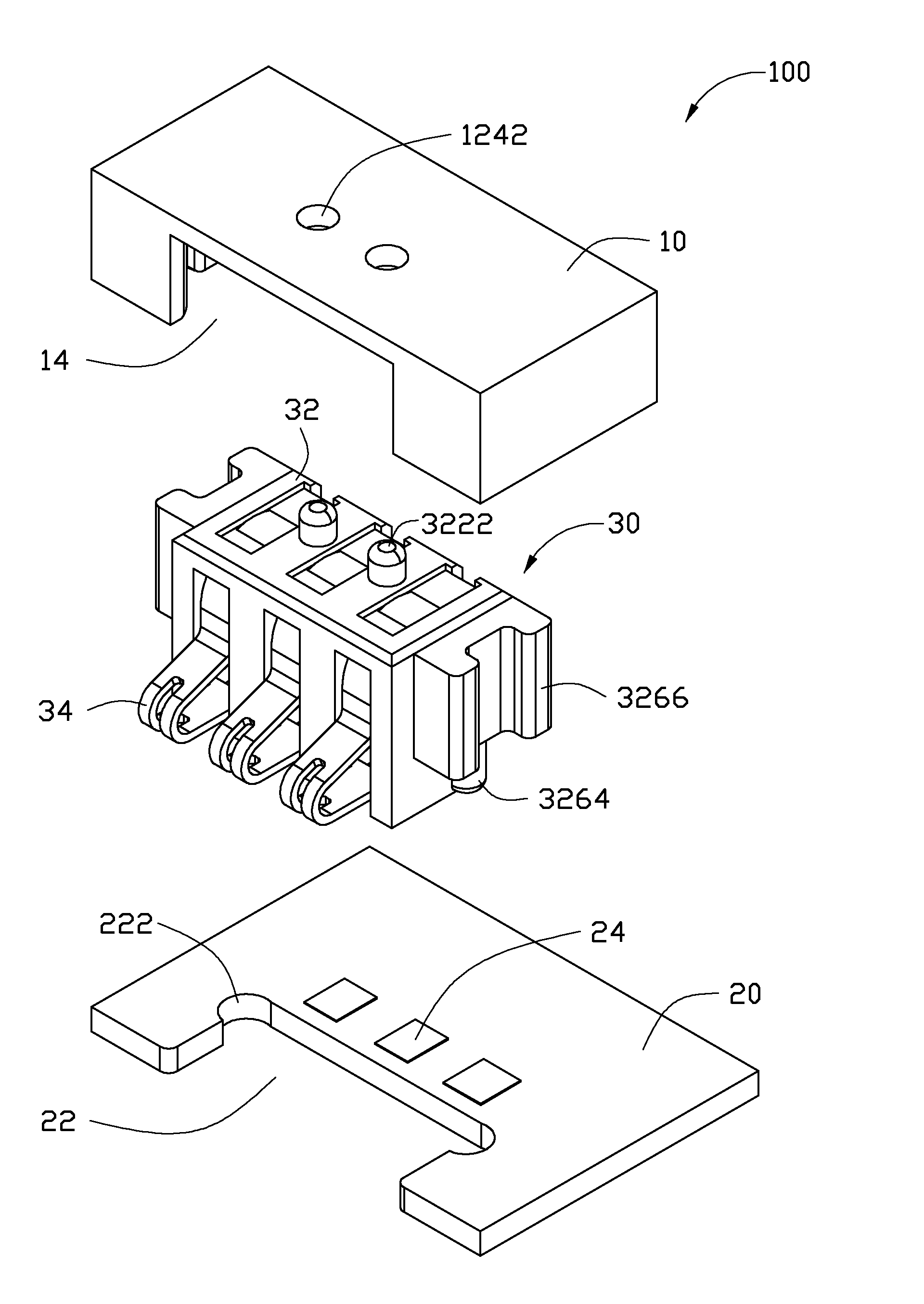
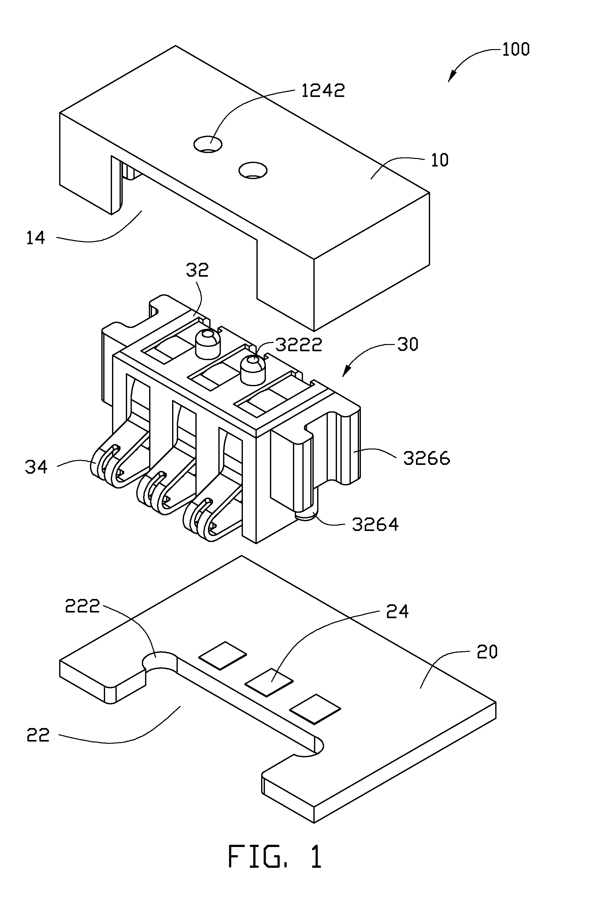
[0012]Referring to FIGS. 1 and 3, an electronic device 100 includes a housing 10, a circuit board 20 and a connector 30 mounted between the housing 10 and the circuit board 20. The connector 30 is used for electrically connecting the circuit board 20 to an electronic element (not shown) of the electronic device, such as a battery.

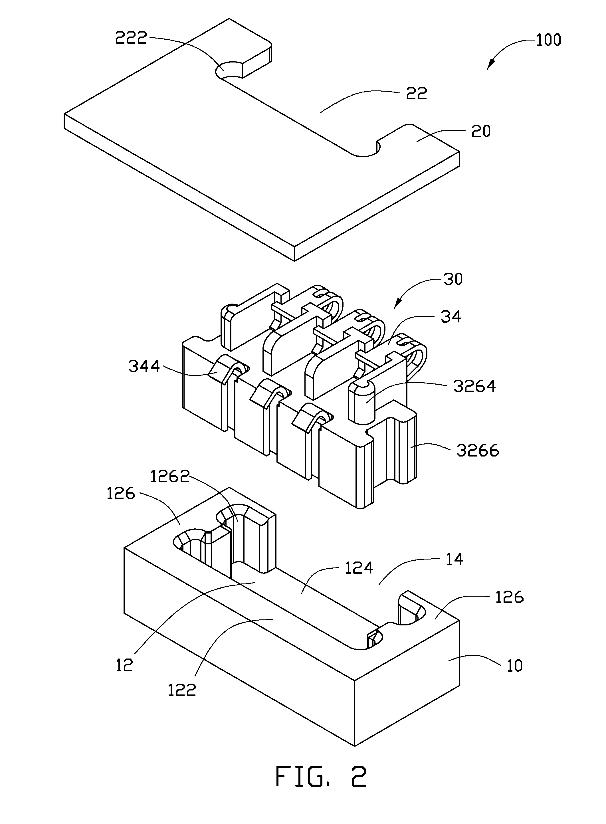
[0013]Referring to FIGS. 1 and 2, the housing 10 defines a receptacle 12 for accommodating the connector 30 and a notch 14 communicating with the receptacle 12. The receptacle 12 is enclosed by a sidewall 122, a base wall 124 and two opposite end walls 126. The housing 10 further defines two spaced positioning holes 1242 defined in the base wall 124. The positioning holes 1242 are for precisely aligning the connector 30 within the receptacle 12. Each end wall 126 defines two spaced latching slots 1262 for latching the connector 30 in the receptacle 12.

[0014]Referring to FIG. 1, the circuit board 20 defines an opening 22 for accommodating the connector 30 an...


PUM


Abstract

A connector is latched to a circuit board, the connector comprises a main body. The main body comprises two opposite ends, each end of the main body having a securing protrusion protruding therefrom, the securing protrusion for latching the connector to the circuit board.

Description

BACKGROUND[0001]1. Technical Field[0002]This exemplary disclosure generally relates to connectors, and particularly to connectors used in electronic devices.[0003]2. Description of Related Art[0004]Commonly, portable electronic devices such as mobile phones use connectors that are mounted to printed circuit boards by surface mounted technology. However, the surface mounting technology can be complicated, and can not easily allow detachment of the connectors from printed circuit boards after connectors are mounted to printed circuit boards.[0005]Therefore, there is room for improvement within the artBRIEF DESCRIPTION OF THE DRAWINGS[0006]Many aspects of the exemplary connector and electronic device using the connector can be better understood with reference to the following drawings. The components in the various drawings are not necessarily drawn to scale, the emphasis instead being placed upon clearly illustrating the principles of the exemplary connector and electronic device usin...

Claims


Application Information

Patent Timeline
IPC IPC(8): H01R12/14H01R13/46
CPCH01R12/7023
Inventor ZHOU, RI
Owner SHENZHEN FUTAIHONG PRECISION IND CO LTD
Why Eureka
Try Eureka