Method for reducing noise coupling in high speed digital systems

a digital system and noise coupling technology, applied in the field of high-speed digital system noise coupling reduction methods and systems, can solve the problems of poor signal integrity in high-speed system, and achieve the effects of reducing noise and cross-talk coupling, reducing noise coupling, and high noise isolation

Inactive Publication Date: 2009-04-30
LENOVO GLOBAL TECH INT LTD
View PDF6 Cites 0 Cited by
  • Summary
  • Abstract
  • Description
  • Claims
  • Application Information

AI Technical Summary

Benefits of technology

[0007]Currently, many techniques have been proposed to reduce noise and cross-talk coupling, but often rely on complex digital signal processing (DSP) techniques and filtering algorithms to achieve noise isolation.
[0008]There is currently a need to detect and implement, and at the same time, achieve high noise isolation.
[0009]Exemplary embodiments include a printed circuit board apparatus having reduced noise coupling, the apparatus including a core layer having an upper and lower surface, the upper and lower surface each including a copper sheet layer, a pre-preg layer having an upper surface and a lower surface, the upper surface of the pre-preg layer coupled to the lower surface of the core layer, a core insulating layer having an upper surface and a lower surface, the upper surface of the core insulating layer coupled to the lower surface of the pre-preg layer, a return current reference layer disposed on the lower surface of the core insulator layer and high-speed signal traces disposed on the upper surface of the core insulating layer, each of the high speed signal traces disposed on a pedestal defined by a section of the pre-preg layer and the core insulating layer, each pedestal being separated by an air gap disposed between adjacent pedestals.

Problems solved by technology

Cross-talk noise coupling on adjacent nets 125 (i.e., victim nets) can result in poor signal integrity in high speed system.
Currently, many techniques have been proposed to reduce noise and cross-talk coupling, but often rely on complex digital signal processing (DSP) techniques and filtering algorithms to achieve noise isolation.

Method used


Image

  • Method for reducing noise coupling in high speed digital systems
  • Method for reducing noise coupling in high speed digital systems
  • Method for reducing noise coupling in high speed digital systems

Examples


Embodiment Construction

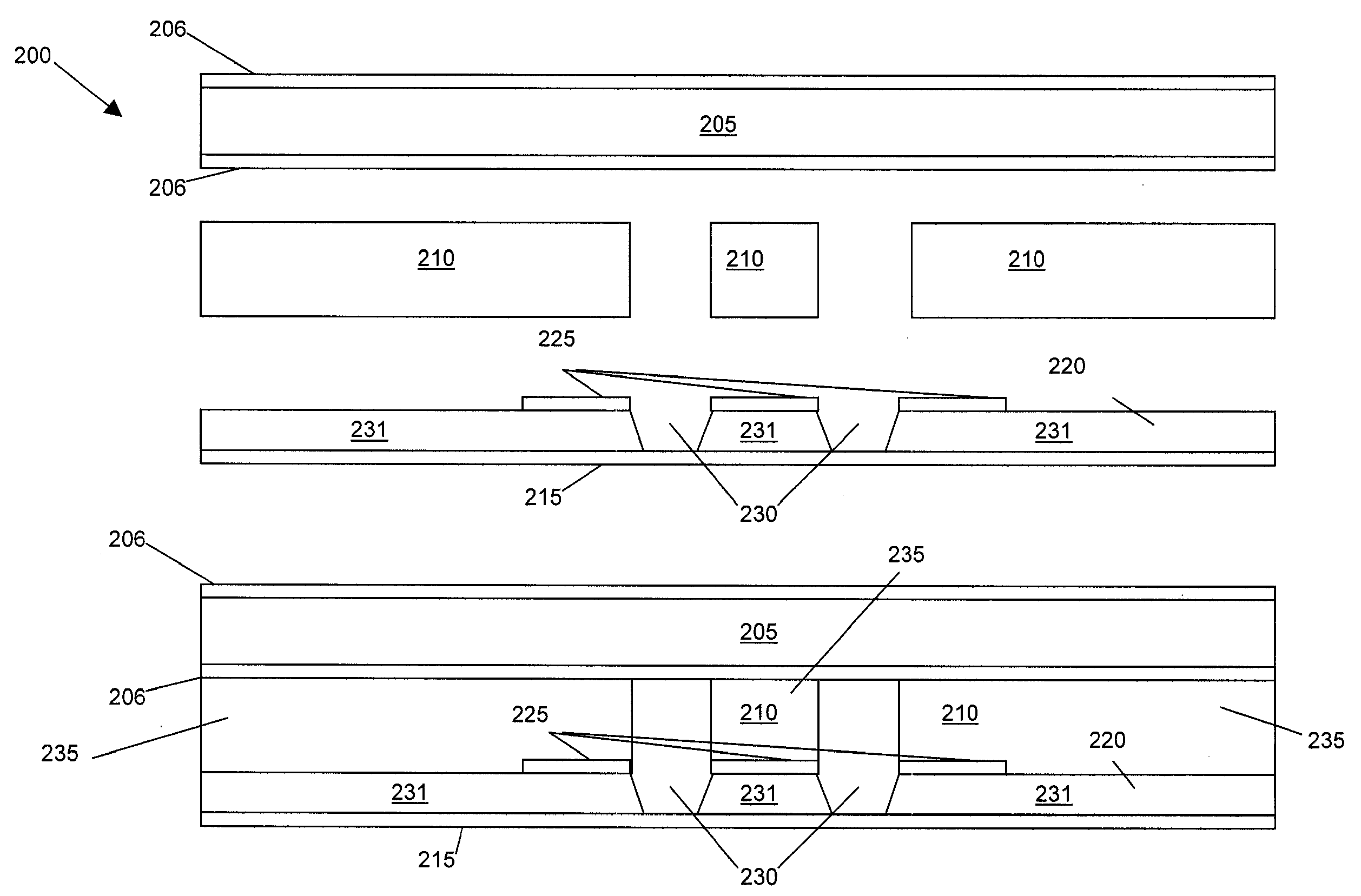
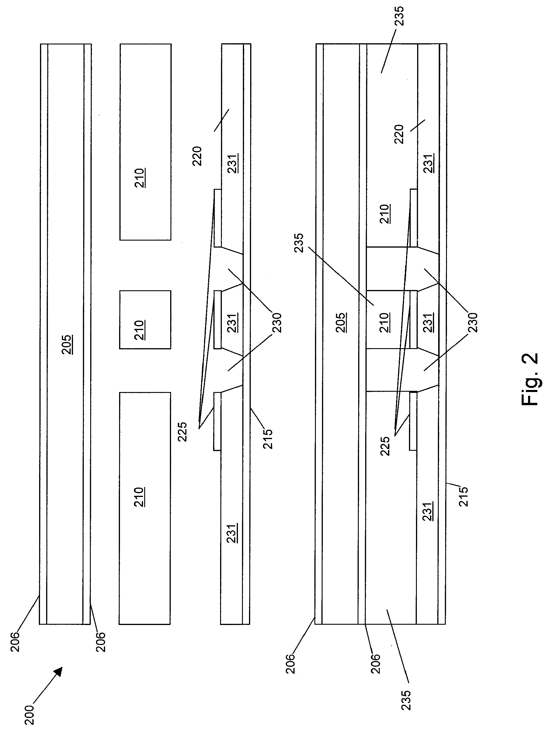
[0021]In exemplary embodiments, the systems and methods described herein reduce cross-talk coupling or noise induction created by capacitive and inductive coupling. Capacitive coupling occurs due to the presence of dielectric medium. In exemplary embodiments, the systems and methods described herein include adjacent printed circuit board (PCB) stripline structures that are surrounded with air. A PCB trace on an inner layer is supported in an air cavity by a pedestal of insulating material. The pedestal is created by digging trenches in core laminate and pre-preg. In exemplary embodiments, pre-preg (pre-impregnated) refers to a layer of exemplary structures described herein, of insulation material inserted between the etched cores. In exemplary embodiments, the pre-preg can be a combination of mat, fabric, non-woven material or roving with resin, usually cured to the B-stage, ready for molding. A standard pre-preg contains more resin than is desired in the finished part; excess resin...


PUM

PropertyMeasurementUnit
speedaaaaaaaaaa
widthaaaaaaaaaa
speed digitalaaaaaaaaaa

Abstract

Methods and systems for reducing noise coupling in high-speed digital systems. Exemplary embodiments include a method, including etching a plurality of high speed signal traces onto a core insulating layer, forming trenches on respective sides of the plurality of high speed signal traces, thereby removing insulating material adjacent to the plurality of high speed signal traces and forming pedestals having remaining insulating material, the plurality of high speed signal traces disposed on and coupled to the remaining insulating material, coupling pre-preg material on the high speed signal traces, removing the pre-preg material adjacent the trenches, thereby retaining the pre-preg material aligned with the high speed signal traces, and heating and pressing a core layer to the pre-preg layer, and heating and pressing the pre-preg layer to the core insulating layer.

Description

CROSS-REFERENCE TO RELATED APPLICATIONS[0001]This application is a continuation of U.S. patent application Ser. No. 11 / 924,416, filed Oct. 25, 2007, the disclosure of which is incorporated by reference herein in its entirety.TRADEMARKS[0002]IBM® is a registered trademark of International Business Machines Corporation, Armonk, N.Y., U.S.A. Other names used herein may be registered trademarks, trademarks or product names of International Business Machines Corporation or other companies.BACKGROUND[0003]1. Field[0004]This invention relates to printed circuit board fabrication, and particularly to methods and systems for reducing noise coupling in high-speed digital systems.[0005]2. Description of Background[0006]FIG. 1 illustrates a conventional printed circuit board having a core layer 105 having a return current reference layer 106, a pre-preg layer 110 and a core insulator layer 120 having a return current reference layer 115 and a number of single layer nets 125. Cross-talk noise co...

Claims


Application Information

Patent Timeline
Patent Type & Authority Applications(United States)
IPC IPC(8): H05K3/02B29C53/00
CPCH05K1/024H05K3/4611H05K3/4697H05K2201/09236H05K2201/09318H05K2203/063Y10T29/49126Y10T29/4913Y10T29/49158Y10T29/49117Y10T29/49165Y10T29/49155Y10T156/1013
Inventor CASES, MOISESHERRMAN, BRADLEY D.HOWIESON, KENT B.MATOGLU, ERDEMMUTNURY, BHYRAV M.PATEL, PRAVIN S.PHAM, NAM H.WESLEY, CALEB J.
Owner LENOVO GLOBAL TECH INT LTD
Why Eureka
Try Eureka