Packing Method and Unit for Folding a Sheet of Packing Material about an Article Such as a Group of Cigarettes

Inactive Publication Date: 2011-12-15
GD SPA
6 Cites 2 Cited by

AI-Extracted Technical Summary

Problems solved by technology

Despite the gripping action of the pusher and counter-pusher, however, a far from negligible percentage of the groups of cigarettes have bee...

Method used

[0030]Packing unit 11 described has numerous advantages. In particular, it is cheap and easy to produce, by only differing in minor respects, that are easy to implement, from similar known packing units. Moreover, in packing unit 11 described, group 2 of cigarettes, as it is transferred enclosed in tubular sheet 3 of packing material, is also retained laterally by lateral appendixes 28, and so undergoes no deformation or slippage as i...

Benefits of technology

[0005]It is an object of the present invention to provide a packing method and unit for folding a sheet of packing material ab...

Abstract

A packing method and unit (11) for folding a sheet (3) of packing material about a group (2) of cigarettes, and having: a first packing conveyor (12) having a first pocket (14) for receiving the group (2) wrapped in the tubular-folded sheet (3) of packing material; a second packing conveyor (18) having a second pocket (20) for receiving the group (2) wrapped in the tubular-folded sheet (3) of packing material; and a transfer device (24) which transfers the group (2), wrapped in the tubular-folded sheet (3) of packing material, from the first pocket (14) to the second pocket (20), and has a pusher (26) located at the first pocket (14) and engaging a first base wall (4) of the group (2), and a counter-pusher (27) located at the second pocket and engaging a second base wall (4), opposite the first base wall (4), of the group (2); the pusher (26) and/or the counter-pusher (27) of the transfer device (24) having respective lateral appendixes (28) which engage minor lateral walls (6) of the group (2), when the pusher (26) and counter-pusher (27) rest on the respective base walls (4) of the group (2), to fold portions (9) of the tubular sheet (3) of packing material onto the minor lateral walls (6) of the group (2).

Application Domain

Packaging cigaretteWrapper folding/bending apparatus +1

Technology Topic

Image

  • Packing Method and Unit for Folding a Sheet of Packing Material about an Article Such as a Group of Cigarettes
  • Packing Method and Unit for Folding a Sheet of Packing Material about an Article Such as a Group of Cigarettes
  • Packing Method and Unit for Folding a Sheet of Packing Material about an Article Such as a Group of Cigarettes

Examples

  • Experimental program(1)

Example

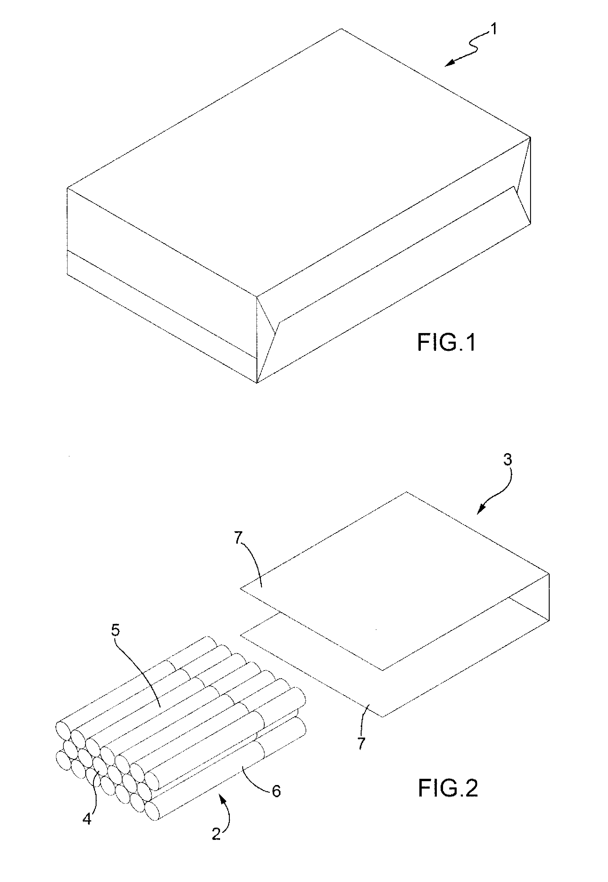
[0015]Number 1 in FIG. 1 indicates as a whole a package of cigarettes comprising a parallelepiped-shaped group 2 of cigarettes (shown in FIG. 2) wrapped in a sheet 3 of foil packing material (shown more clearly in FIG. 2). Once sheet 3 of packing material is folded about group 2 of cigarettes to form package 1, the shape of package 1 is stabilized by gluing or heat sealing the superimposed portions of sheet 3 of packing material. Alternatively, package 1 may not be stabilized, e.g. because it is eventually to be inserted inside an outer package (not shown).
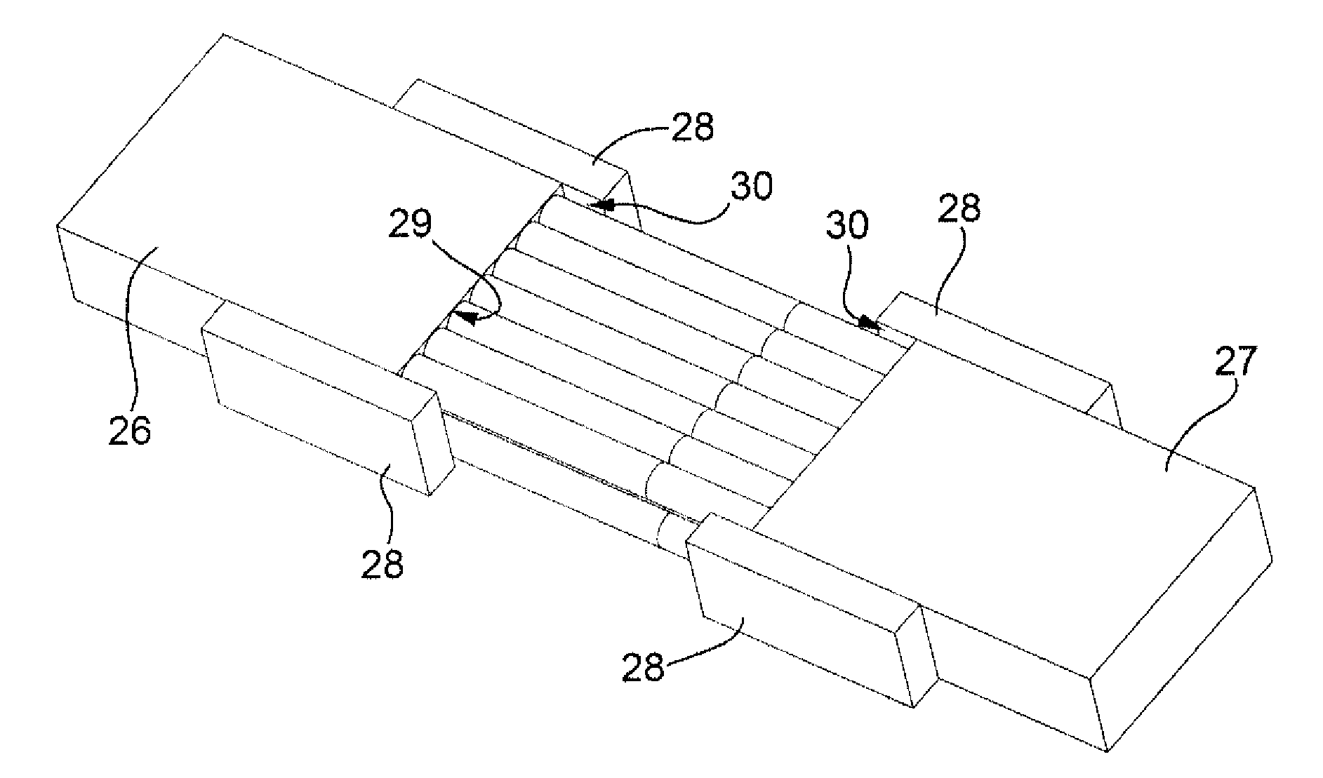
[0016]As shown in FIG. 2, group 2 of cigarettes comprises two opposite base walls 4 (only one shown in FIG. 2) defined by the ends of the cigarettes; two opposite major lateral walls 5 (only one shown in FIG. 2) defined by the cylindrical lateral walls of the cigarettes; and two opposite minor lateral walls 6 (only one shown in FIG. 2) defined by the cylindrical lateral walls of the cigarettes.
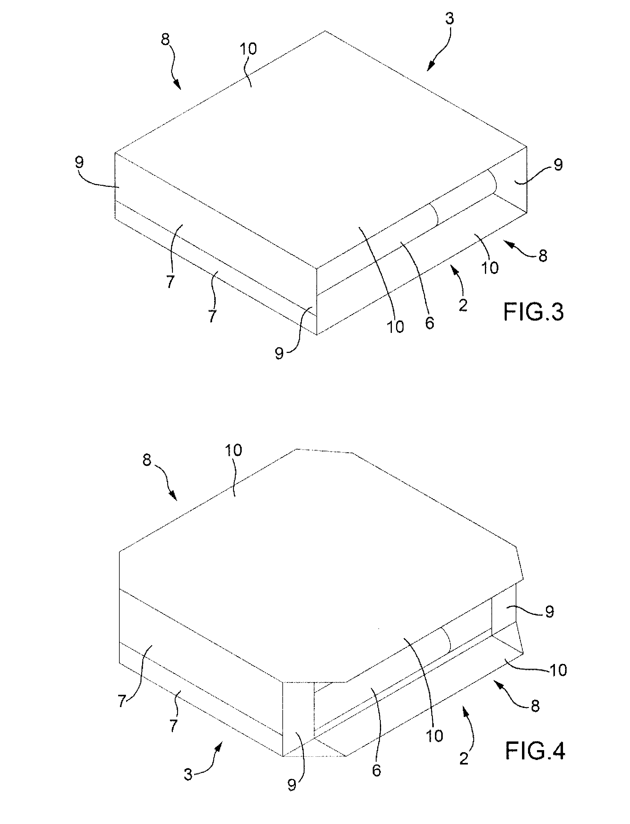
[0017]As shown in FIGS. 2 and 3, folding sheet 3 of packing material about group 2 of cigarettes comprises folding sheet 3 of packing material into a U about group 2 of cigarettes, and then folding one on top of the other and onto a base wall 4 of group 2 of cigarettes two flaps 7 of the U-folded sheet 3 of packing material projecting from base wall 4, so as to form a tubular sheet 3 of packing material (FIG. 3) having two open lateral ends 8 at the minor lateral walls 6 of group 2 of cigarettes. As shown in FIG. 4, four portions 9 of the open lateral ends 8 of the tubular sheet 3 of packing material are first folded onto minor lateral walls 6 of group 2 of cigarettes. That is, the portions 9 of open lateral ends 8 of tubular sheet 3 of packing material coplanar with the base walls 4 of group 2 of cigarettes are folded 90° onto minor lateral walls 6 of group 2 of cigarettes, and about minor transverse edges of base walls 4 of group 2 of cigarettes. Once portions 9 are folded, the other flaps 10 of open lateral ends 8 of tubular sheet 3 of packing material are folded one on top of the other and onto minor lateral walls 6 of group 2 of cigarettes to complete folding sheet 3 of packing material and form package 1 as shown in FIG. 1.
[0018]Number 11 in FIG. 5 indicates as a whole a packing unit for folding a respective sheet 3 of packing material about each group 2 of cigarettes to form a package 1 as shown in FIG. 1. Packing unit 11 comprises a packing wheel 12 which rotates in steps (anticlockwise in FIG. 5) about a horizontal axis of rotation 13 and supports a number of peripheral seats 14, each for housing a group 2 of cigarettes.
[0019]At a feed station 15, each pocket 14 on packing wheel 12 receives a group 2 of cigarettes, which is pushed into pocket 14 by a pusher 15. Also at feed station 15, a flat sheet 3 of packing material, gummed beforehand if necessary, is fed, perpendicularly to the path of group 2 of cigarettes, into position in front of the inlet of pocket 14, so group 2 of cigarettes intercepts sheet 3 of packing material, thus folding sheet 3 of packing material into U about group 2 of cigarettes.
[0020]Once a group 2 of cigarettes, enclosed in a U-folded sheet 3 of packing material, is inserted inside a pocket 14, the two flaps 7 of the U-folded sheet 3 of packing material projecting from pocket 14 are folded one on top of the other and onto group 2 of cigarettes to form a tubular sheet 3 of packing material. More specifically, during a stop of packing wheel 12, a movable folder 16 folds the rear flap 7 (in the same direction as the rotation direction of packing wheel 12) onto group 2 of cigarettes; and, during the next forward movement of packing wheel 12, a fixed folder 17 folds the front flap 7 (in the opposite direction to the rotation direction of packing wheel 12) onto group 2 of cigarettes and on top of the already folded rear flap 7.
[0021]Packing unit 11 comprises a packing wheel 18 which is located alongside packing wheel 12, rotates in steps (anticlockwise in FIG. 5) about a horizontal axis of rotation 19 parallel to axis of rotation 13 of packing wheel 12, and supports a number of peripheral pockets 20, each for housing a group 2 of cigarettes. At a transfer station 21 between the two packing wheels 12 and 18, each group 2 of cigarettes enclosed in tubular sheet 3 of packing material is expelled from pocket 14 of packing wheel 12 into a pocket 20 of packing wheel 18.
[0022]Packing wheel 18 comprises a movable folder 22 which is located at transfer station 21, has two folding members (only one shown in FIG. 5) on opposite sides of pocket 20, and moves back and forth to fold the rear flaps 10 of open lateral ends 8 of tubular sheet 3 of packing material. Packing wheel 18 also comprises a fixed folder 23 which is located at transfer station 21, has two folding members (only one shown in FIG. 5) on opposite sides of pocket 20, and folds the front flaps 10 of open lateral ends 8 of tubular sheet 3 of packing material as step rotation of packing wheel 18 moves pocket 20 forward.
[0023]Transfer station 21 is equipped with a transfer device 24, which transfers group 2 of cigarettes, enclosed in tubular sheet 3 of packing material, from pocket 14 of packing wheel 12 to pocket 20 of packing wheel 18 in a transfer direction 25 perpendicular to axes of rotation 13 and 19. Transfer device 24 comprises a pusher 26 which is located at pocket 14 (i.e. at packing wheel 12), is mounted to move in transfer direction 25, and engages a base wall 4, located upstream in transfer direction 25, of group 2 of cigarettes. Transfer device 24 also comprises a counter-pusher 27 which is located at pocket 20 (i.e. at packing wheel 18), is mounted to move in transfer direction 25, and engages a base wall 4, located downstream in transfer direction 25 and opposite the upstream base wall 4, of group 2 of cigarettes.
[0024]To transfer group 2 of cigarettes enclosed in tubular sheet 3 of packing material, pusher 26 and counter-pusher 27 grip group 2 of cigarettes between them as it is being transferred. In other words, pusher 26 moves in transfer direction 25 into contact with the corresponding base wall 4 of group 2 of cigarettes, and, at the same time, counter-pusher 27 moves in the opposite direction to transfer direction 25 into contact with the corresponding base wall 4 of group 2 of cigarettes; at which point, pusher 26 and counter-pusher 27 grip group 2 of cigarettes between them and move together in transfer direction 25 to transfer group 2 of cigarettes from pocket 14 of packing wheel 12 to pocket 20 of packing wheel 18. Once group 2 of cigarettes is transferred, pusher 26 moves back to its original position behind pocket 14 of packing wheel 12, moving in the opposite direction to the transfer movement.
[0025]Pusher 26 and counter-pusher 27 of transfer device 24 comprise respective lateral appendixes 28 which, as pusher 26 and counter-pusher 27 come to rest on respective base walls 4 of group 2 of cigarettes, engage the minor lateral walls 6 of group 2 of cigarettes, thus folding portions 9 of sheet 3 of packing material onto minor lateral walls 6 of group 2 of cigarettes. More specifically, pusher 26 and counter-pusher 27 of transfer device 24 comprise respective end walls 29, each of which is parallel to and faces a respective base wall 4 of group 2 of cigarettes, rests against respective base wall 4 during transfer, and is flanked by the corresponding two lateral appendixes 28; and each lateral appendix 28 projects from its own end wall 29 towards the other end wall 29.
[0026]In the FIGS. 8 and 9 embodiment, each lateral appendix 28 is parallelepiped-shaped with a rectangular base, and has a flat folding wall 30 which holds respective portion 9 folded down and is parallel to transfer direction 25 and perpendicular to the corresponding base wall 4 of group 2 of cigarettes (i.e. perpendicular to corresponding end wall 29). In a different embodiment not shown, each lateral appendix 28 is parallelepiped-shaped with a triangular base and with folding wall 30 along the hypotenuse.
[0027]In the FIGS. 10 and 11 variation, each lateral appendix 28 is substantially truncated-pyramid-shaped with a triangular base and with folding wall 30 along the hypotenuse; in which case, folding wall 30 for holding respective portion 9 folded down is flat, forms an acute angle with transfer direction 25, and forms an obtuse angle with the corresponding base wall 4 of group 2 of cigarettes (i.e. forms an obtuse angle with the corresponding end wall 29).
[0028]It is important to note that the movement of pusher 26 and counter-pusher 27 is timed with the action of movable pusher 22 and fixed pusher 23, so that, when appendixes 28 disengage portions 9, folders 22 and 23 fold the open ends 8 of tubular sheet 3 of packing material over the folded portions 9 to prevent portions 9 from springing back up. In an alternative embodiment, appendixes 28 are designed so that flaps 10 of open lateral ends 8 of tubular sheet 3 of packing material can be folded over appendixes 28; in which case, flaps 10 of open lateral ends 8 of tubular sheet 3 of packing material are folded over appendixes 28, which are not withdrawn from group 2 of cigarettes until flaps 10 are at least partly folded.
[0029]In the preferred embodiment described, each sheet 3 of packing material is folded about a group 2 of cigarettes; in a different embodiment not shown, group 2 of cigarettes may be replaced by any parallelepiped-shaped article, such as a package of a food product.
[0030]Packing unit 11 described has numerous advantages. In particular, it is cheap and easy to produce, by only differing in minor respects, that are easy to implement, from similar known packing units. Moreover, in packing unit 11 described, group 2 of cigarettes, as it is transferred enclosed in tubular sheet 3 of packing material, is also retained laterally by lateral appendixes 28, and so undergoes no deformation or slippage as it is transferred between the two packing wheels 12 and 18. Finally, by virtue of lateral appendixes 28, portions 9 of tubular sheet 3 of packing material are folded onto group 2 of cigarettes as it is transferred between the two packing wheels 12 and 18, which means packing wheel 18 need not be equipped with specific folders for portions 9 of tubular sheet 3 of packing material, thus greatly simplifying the design of packing wheel 18.

PUM

no PUM

Description & Claims & Application Information

We can also present the details of the Description, Claims and Application information to help users get a comprehensive understanding of the technical details of the patent, such as background art, summary of invention, brief description of drawings, description of embodiments, and other original content. On the other hand, users can also determine the specific scope of protection of the technology through the list of claims; as well as understand the changes in the life cycle of the technology with the presentation of the patent timeline. Login to view more.

Similar technology patents

Appliance for distributing a precut wiping material that is rolled up or folded in a Z shape

InactiveUS9408505B2Cheap to implementEffective interventionFilament handlingDomestic applicationsSkin flapCam
Owner:GRANGER MAURICE

Method of folding a sheet of packing material about a group of cigarettes

InactiveUS20090320414A1Cheap to implementPackaging cigaretteWrapper folding/bending apparatusEngineeringMechanical engineering
Owner:GD SPA

Classification and recommendation of technical efficacy words

  • Cheap to implement

Method of raising a building

Owner:SO L E S SOC LAVORI EDILI E SERBATOI +1

Method of controlling an automatic production/packing machine

InactiveUS20090044491A1Cheap to implementCapsCapping machinery safety/controlManufacturing engineeringControl unit
Owner:GD SPA

Cigarette packing machine for producing rigid hinged-lid packets

InactiveUS20060254212A1Cheap to implementPackaging cigaretteWrapper folding/bending apparatusCigarette packEngineering
Owner:GD SPA
Why Eureka
Try Eureka