Unit and method of feeding containers arranged in a number of superimposed rows

Inactive Publication Date: 2006-05-04
GD SPA
9 Cites 2 Cited by

AI-Extracted Technical Summary

Problems solved by technology

This is due to the way in which known reject stations are built and operate, which does not permit removal from the stream of a single packet stacked with another.
When a packet of cigarettes is pushed along the respective channel at the heat-shrink station, the major lateral walls of the packet of cigarettes...

Benefits of technology

[0008] It is an object of the present invention to provide a unit and method of feeding containers arranged in a number of superimposed...

Abstract

A unit and method for feeding containers, whereby the containers, arranged in two superimposed rows, are fed along a horizontal path and through a reject station; upstream from the reject station, two superimposed containers are parted, by translation in a vertical direction, so as to travel, separately and facing each other, along the next portion of the path; immediately downstream from the reject station, two facing containers are brought back into contact with each other so as to travel, superimposed, along the next portion of the path; and the reject station has a first reject device for expelling only one container in a bottom row from the path, and a second reject device for expelling only one container in a top row from the path.

Application Domain

Wrappers shrinkagePackaging cigarette +4

Technology Topic

EngineeringMechanical engineering

Image

  • Unit and method of feeding containers arranged in a number of superimposed rows
  • Unit and method of feeding containers arranged in a number of superimposed rows
  • Unit and method of feeding containers arranged in a number of superimposed rows

Examples

  • Experimental program(1)

Example

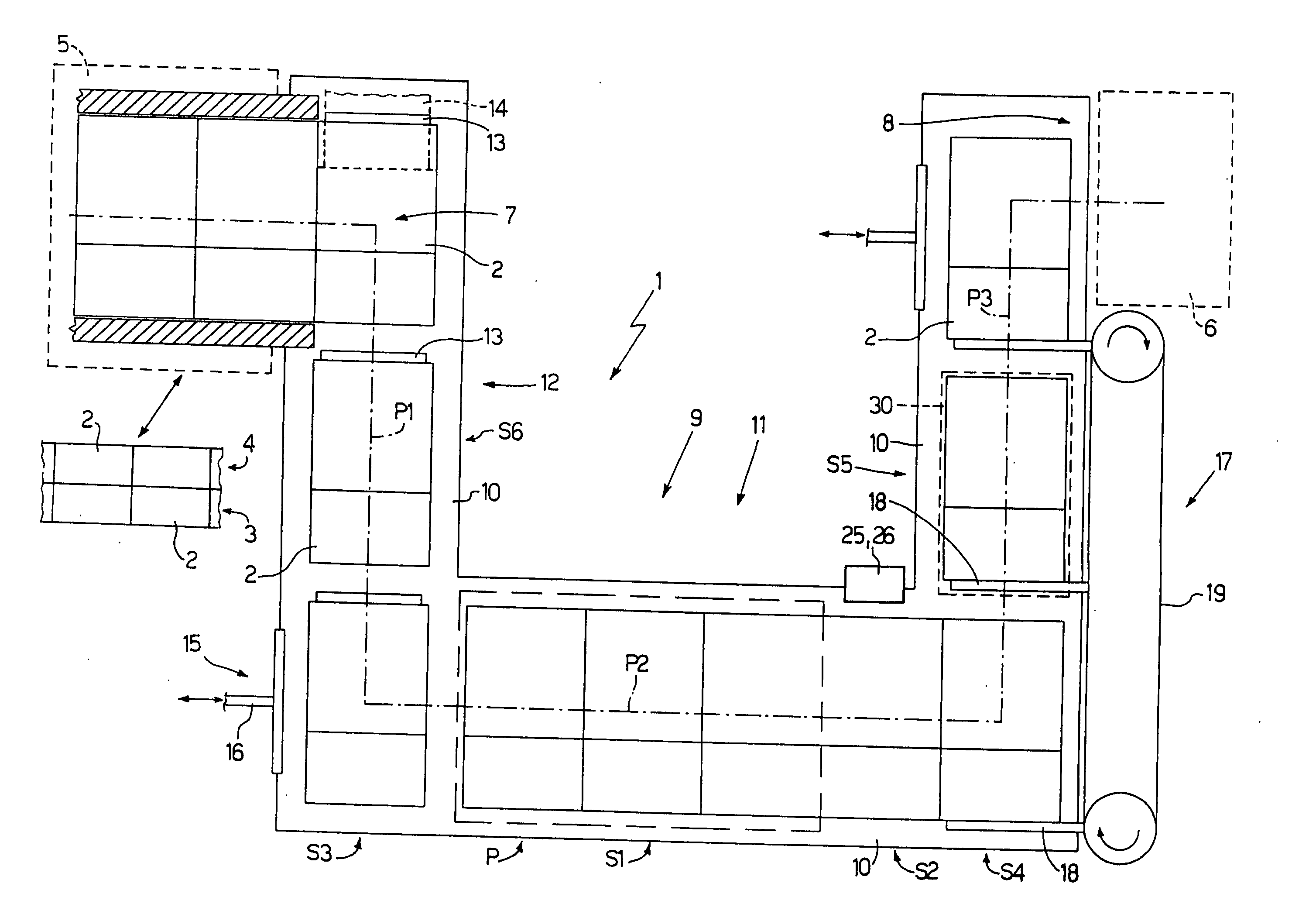
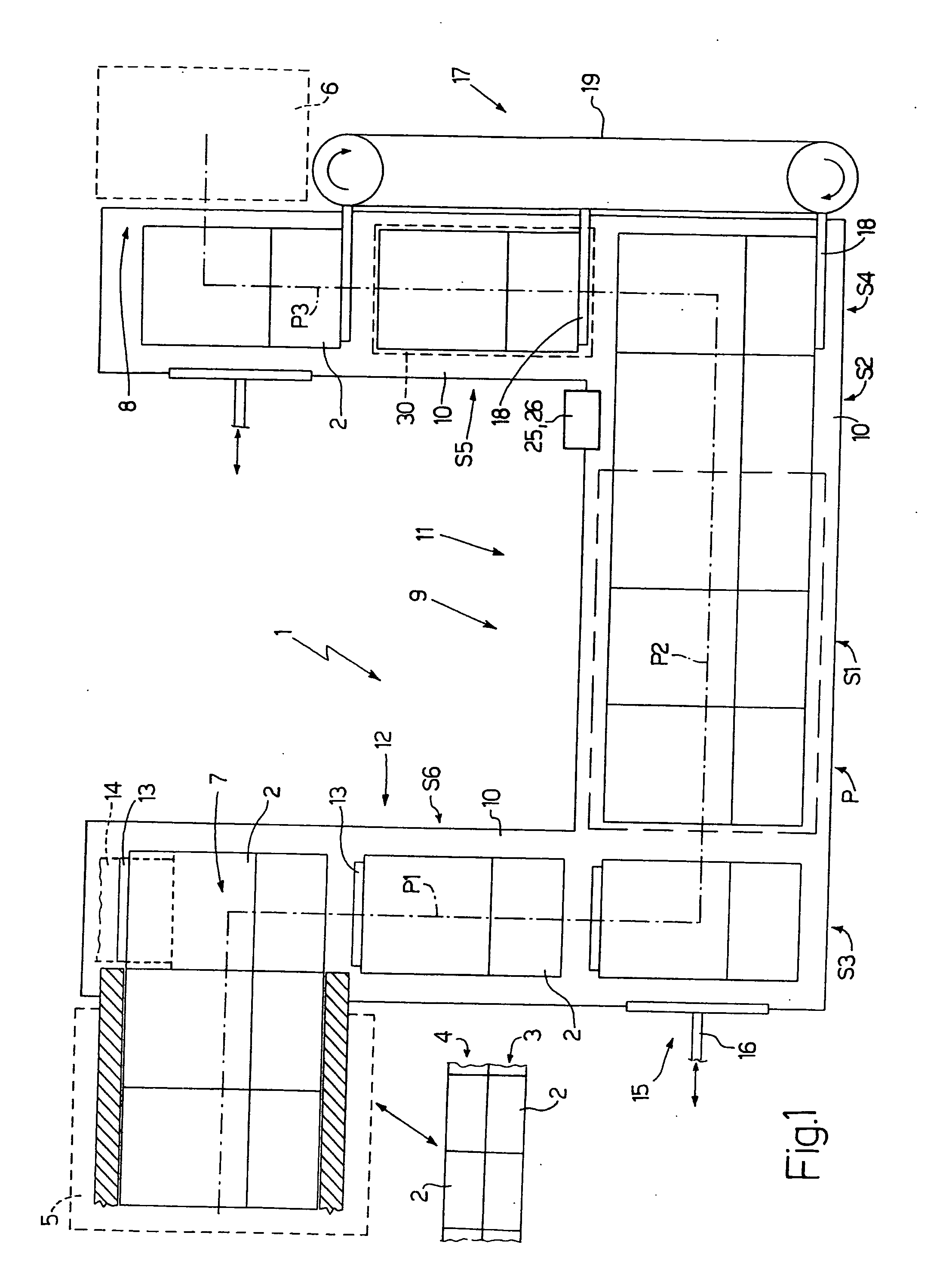
[0015] Number 1 in FIG. 1 indicates as a whole a feed unit for feeding containers or packets 2 of cigarettes arranged in two superimposed, respectively bottom and top, rows 3 and 4. Feed unit 1 forms part of a cigarette packing line comprising a cellophaning machine 5 for applying an overwrapping of transparent plastic material to packets 2 of cigarettes; and a cartoning machine 6 for producing cartons of packets 2 of cigarettes. More specifically, feed unit 1 is interposed between cellophaning machine 5 and cartoning machine 6, receives a succession of packets 2 of cigarettes from an output 7 of cellophaning machine 5, and transfers the succession of packets 2 of cigarettes to an input 8 of cartoning machine 6.
[0016] Feed unit 1 comprises a conveying device 9 for feeding packets 2 along a horizontal U-shaped path P extending from output 7 of cellophaning machine 5 to input 8 of cartoning machine 6. More specifically, path P comprises a linear start portion P1; a linear intermediate portion P2 perpendicular to start portion P1; and a linear end portion P3 parallel to start portion P1.
[0017] Conveying device 9 comprises a U-shaped slide surface 10 parallel to path P and for supporting packets 2 in sliding manner; and a push device 11 for pushing packets 2 along slide surface 10. Push device 11 comprises a pusher 12 having a number of push members 13 fitted to an endless belt 14 (shown only partly), and which pushes packets 2 along start portion P1; a pusher 15 having a 16 with a linear reciprocating movement, and which pushes packets 2 along intermediate portion P2; and a pusher 17 having a number of push members 18 fitted to an endless belt 19, and which pushes packets 2 along end portion P3.
[0018] As shown in FIG. 2, a heat-shrink station S1, for heat treating each packet 2, and a reject station S2, for expelling any faulty packets 2 from path P, are arranged in succession along intermediate portion P2 of path P.
[0019] Upstream from heat-shrink station S1, and therefore upstream from reject station S2, is located a parting station S3 where two superimposed packets 2 are parted by translation in a vertical direction D perpendicular to path P, so as to travel separately and facing each other along the next portion of path P. Immediately downstream from reject station S2, and therefore downstream from heat-shrink station S1, is located a stacking station S4 where two facing packets 2 are brought back into contact with each other by translation in a vertical direction D, so as to travel, superimposed, along the next portion of path P.
[0020] In other words, rows 3 and 4 of packets 2 travel, superimposed, along path P with the exception of the portion of intermediate portion P2 of path P extending between parting station S3 and stacking station S4; along which portion, rows 3 and 4 of packets 2 are fed parted and facing each other by conveying device 9, and in particular pusher 15.
[0021] Heat-shrink station S1 comprises a further two slide surfaces 20 and 21, which are parallel to and face slide surface 10 to define, with slide surface 10, two channels 22 and 23, along which respective rows 3 and 4 of packets 2 are fed. More specifically, the bottom row 3 of packets slides along slide surface 10 and inside channel 22 defined between slide surface 10 and slide surface 20, while the top row 4 of packets slides along slide surface 20 and inside channel 23 defined between slide surface 20 and slide surface 21.
[0022] Slide surfaces 10, 20, 21 comprise electric heating elements (not shown), which are embedded inside slide surfaces 10, 20, 21 and controlled to heat channels 22, 23 to a given temperature, which normally depends on the travelling speed of packets 2 along path P, and on the type of plastic overwrapping material (not shown) applied to packets 2.
[0023] In a preferred embodiment, slide surfaces 10 and 21 at heat-shrink station S1 are movable in a vertical direction D perpendicular to path P, and heat-shrink station S1 comprises two actuating devices 24 for moving slide surfaces 10 and 21 cyclically in vertical direction D perpendicular to path P, so as to move slide surfaces 10 and 21 cyclically towards and away from slide surface 20. In a preferred embodiment, both actuating devices 24 form part of the same mechanism, i.e. are powered by a common motor. In an alternative embodiment, the two actuating devices 24 are mechanically independent.
[0024] More specifically, conveying device 9 feeds packets 2 along path P with an intermittent movement comprising a cyclic succession of travelling steps and hold steps. And actuating devices 24 are timed with conveying device 9 to keep slide surfaces 10 and 21 close to slide surface 20 during the hold steps, and away from slide surface 20 during the travelling steps in the intermittent movement. This has the dual effect of permitting unimpeded travel of packets 2 along path P, and increasing heat transmission to packets 2 by virtue of sliding surfaces 10, 20, 21 firmly contacting packets 2.
[0025] The actual size of packets 2 varies fairly widely on account of inevitable tolerances as regards both materials and packing processes. Between each actuating device 24 and respective slide surface 10, 21, an elastic member 24a is therefore preferably interposed to allow a certain amount of flexible self-adjustment of the position of slide surface 10, 21 in vertical direction D. This is particularly useful by enabling slide surfaces 10 and 21 to adapt automatically to the actual size of packets 2.
[0026] In other words, by means of elastic members 24a, substantially constant pressure is applied on each packet 2 regardless of the actual size of packet 2.
[0027] By way of example, each elastic member 24a interposed between each actuating device 24 and respective slide surface 10, 21 is defined by a spring, a pneumatic shock absorber, or an elastomer.
[0028] Reject station S2 comprises a reject device 25 for only expelling one bottom packet 2, i.e. in bottom row 3 of packets 2, from path P; and a reject device 26 for only expelling one top packet 2, i.e. in top row 4 of packets 2, from path P. Each reject device 25, 26 preferably comprises a pneumatic push device (not shown in detail) for pushing a packet 2 off path P in a horizontal direction perpendicular to path P.
[0029] Slide surface 20 ends at stacking station S4, so that the packets 2 in top row 4 travelling along slide surface 20 are eventually unsupported from underneath and drop by force of gravity onto packets 2 in bottom row 3. In the event a packet 2 in bottom row 3 is expelled at reject station S2, the corresponding packet 2 in top row 4 would have too far to fall at stacking station S4 and may become misaligned, so stacking station S4 comprises a supporting surface 27 movable, in a vertical direction D perpendicular to path P, between a withdrawn position, in which a top face of supporting surface 27 is aligned with a top face of slide surface 10, and a raised position, in which the top face of supporting surface 27 is raised with respect to the top face of slide surface 10.
[0030] When a packet 2 in bottom row 3 and a corresponding packet 2 in top row 4 are both present, supporting surface 27 is maintained in the withdrawn position, and, at the end of slide surface 20, packet 2 in top row 4 drops a short distance vertically onto packet 2 in bottom row 3. When only a packet 2 in top row 4 is present, with no corresponding packet 2 in bottom row 3, supporting surface 27 is moved into the raised position to break the free fall of packet 2 in top row 4 and guide packet 2 down in controlled manner as supporting surface 27 moves back down into the withdrawn position.
[0031] Parting station S3 comprises a supporting surface 28 movable, in a vertical direction D perpendicular to path P, between a withdrawn position, in which a top face of supporting surface 28 is aligned with a top face of slide surface 10, and a raised position, in which the top face of supporting surface 28 is raised with respect to the top face of slide surface 10 and aligned with a top face of slide surface 20. Parting station S3 also comprises a clamping device 29 aligned vertically with supporting surface 28 and for clamping a packet 2 in a given vertical position slightly above slide surface 20. In one embodiment, clamping device 29 comprises a suction member (not shown). In an alternative embodiment, clamping device 29 comprises a gripper (not shown) having two jaws movable in a direction crosswise to path P and in opposition to elastic means.
[0032] In actual use, and as shown in FIGS. 3 to 5, when a packet 2 in bottom row 3 and a corresponding packet 2 in top row 4 reach parting station S3, supporting surface 28 is moved from the withdrawn to the raised position to lift both packet 2 in bottom row 3 and corresponding packet 2 in top row 4 and bring packet 2 in top row 4 into contact with clamping device 29. At this point, packet 2 in top row 4 remains in contact with clamping device 29, and, as supporting surface 28 moves back down into the withdrawn position, is parted from packet 2 in bottom row 3 (resting on supporting surface 28).
[0033] As shown in FIG. 1, a known filler station S5 is located downstream from reject station S2 to transfer a number of packets 2 to conveying device 9 to replace any packets 2 expelled at reject station S2. Filler station S5 comprises a vertical hopper 30 containing a stack of superimposed packets 2 and having an outlet located over conveying device 9.
[0034] As shown in FIG. 6, conveying device 9 preferably comprises a rotation station S6 for rotating each packet 2 by 180° about a vertical axis 31 perpendicular to path P. Rotation station S6 comprises a horizontal turntable 32 having four vertical members 33 projecting upwards from turntable 32 and arranged to enclose packets 2.
[0035] Reject station S2 as described above has numerous advantages by enabling, even in the case of packets of cigarettes arranged in two or more superimposed rows, rejection of either all or only one of the packets in a given stack, regardless of the location of the rejected packet.
[0036] Heat-shrink station S1 as described above has numerous advantages by permitting unimpeded travel of packets 2 along path P, while at the same time increasing heat transmission to packets 2 by virtue of slide surfaces 10, 20, 21 firmly contacting packets 2.
[0037] Given its numerous advantages, feed unit 1 as described above may also be used to advantage at other points along a cigarette packing line, or even on other automatic machines for packing other than cigarettes (e.g. food products).

PUM

PropertyMeasurementUnit
Elasticity

Description & Claims & Application Information

We can also present the details of the Description, Claims and Application information to help users get a comprehensive understanding of the technical details of the patent, such as background art, summary of invention, brief description of drawings, description of embodiments, and other original content. On the other hand, users can also determine the specific scope of protection of the technology through the list of claims; as well as understand the changes in the life cycle of the technology with the presentation of the patent timeline. Login to view more.

Similar technology patents

Method and machine for transferring packets

InactiveUS7108122B2cheap to implement
Owner:GD SPA

Appliance for distributing a precut wiping material that is rolled up or folded in a Z shape

InactiveUS9408505B2cheap to implementeffective intervention
Owner:GRANGER MAURICE

Method and device for applying a label to a packet

InactiveUS20050082012A1cheap to implement
Owner:GD SPA

Method of folding a sheet of packing material about a group of cigarettes

InactiveUS20090320414A1cheap to implement
Owner:GD SPA

Classification and recommendation of technical efficacy words

  • cheap to implement

Method for packing a product using a flat tubular package

InactiveUS6915622B2cheap to implement
Owner:GD SPA

Method of raising a building

ActiveUS20090142140A1cheap to implement
Owner:SO L E S SOC LAVORI EDILI E SERBATOI +1

Cigarette packing machine for producing rigid hinged-lid packets

InactiveUS20060254212A1cheap to implement
Owner:GD SPA

Apparatus and method for stabilizing the frequency of lasers

InactiveUS20070217456A1less complexcheap to implement
Owner:LOCKHEED MARTIN COHERENT TECH
Why Eureka
Try Eureka