
Appliance for distributing a precut wiping material that is rolled up or folded in a Z shape

Inactive Publication Date: 2016-08-09
GRANGER MAURICE
View PDF15 Cites 0 Cited by
  • Summary
  • Abstract
  • Description
  • Claims
  • Application Information

AI Technical Summary

Benefits of technology

The invention simplifies a machine by allowing it to be opened from the bottom and effectively intervenes if cut material becomes jammed. The solution is cheaper to implement and allows for easy replacement of the reel of material. It also enables quick intervention in case of material jamming inside the machine.

Problems solved by technology

Various attempts to design such a machine have been made but have eventually been abandoned due to major unresolved problems relating to the random nature of the pulling force exerted on the material by the user, the direction of this force and the risks of jamming due to material becoming blocked in the machine.
The problem to be resolved then becomes mainly the fact that the wipe material is grasped and removed by users exerting highly variable pulling forces in highly variable directions which interfere with cutting of the strip of material inside the machine and therefore cause malfunctioning.
This is the major difficulty which has prevented the dispensing of pre-cut wipe material wound on a reel.
In practice, transferring the knowledge disclosed in these two solutions does not make it possible to ensure reliable operation and dispensing because the Applicant observed jamming of the mechanisms in question.
Although the operation of the machine described in Patent PCT FR 2009 / 052161 is particularly reliable, the machine nevertheless has certain drawbacks due to its high component count and its therefore considerable manufacturing and assembly costs.
In fact, the operator's movements are obstructed as he grasps and secures the partially finished reel of material that is to be removed and as he reloads the machine with another reel.

Method used


Image

  • Appliance for distributing a precut wiping material that is rolled up or folded in a Z shape
  • Appliance for distributing a precut wiping material that is rolled up or folded in a Z shape
  • Appliance for distributing a precut wiping material that is rolled up or folded in a Z shape

Examples


Embodiment Construction

[0037]In order that the object of the invention may more readily be understood, the following description is given, merely by way of example, reference being made to the accompanying drawings.

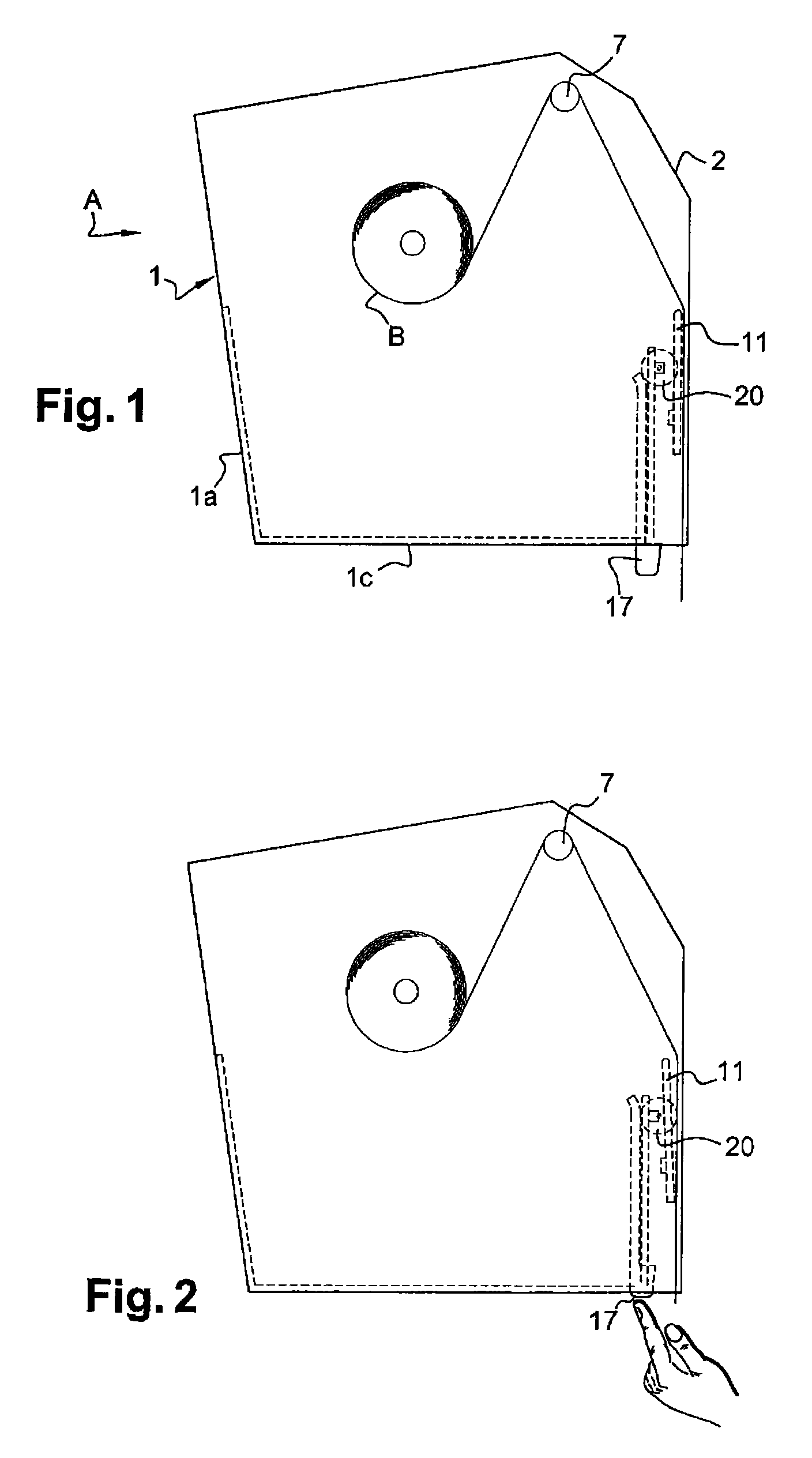
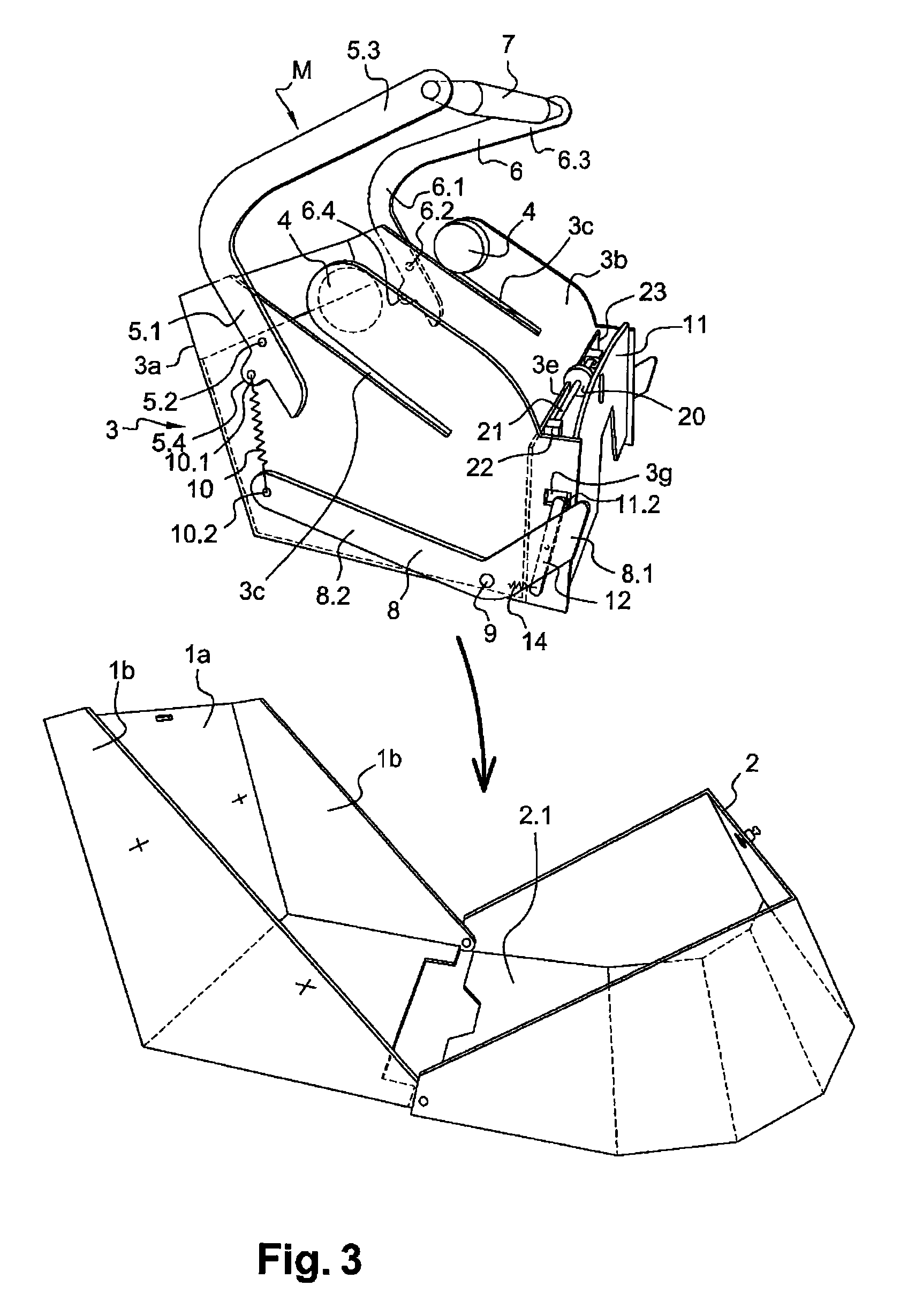
[0038]The dispensing machine for pre-cut wipe material is represented in its entirety as (A) and comprises a wall-mounted housing (1) with a back panel (1a), two side panels (1b), a lower base panel (1c) and a cover (2) which is articulated relative to the housing so that it can be closed by lifting it upwards and locking it. The housing is capable of receiving a module (3) which itself has a back panel (3a) and two lateral side pieces (3b) shaped and designed in a known manner in order to receive reel (B) of pre-cut wipe material. The reel of material is held by end pieces (4) or convex shapes on the lateral side pieces (3b) of the module with at least one of the side pieces or parts of the side pieces having the capacity of elastic deformation in a known manner in order to make it possible to...


PUM


Abstract

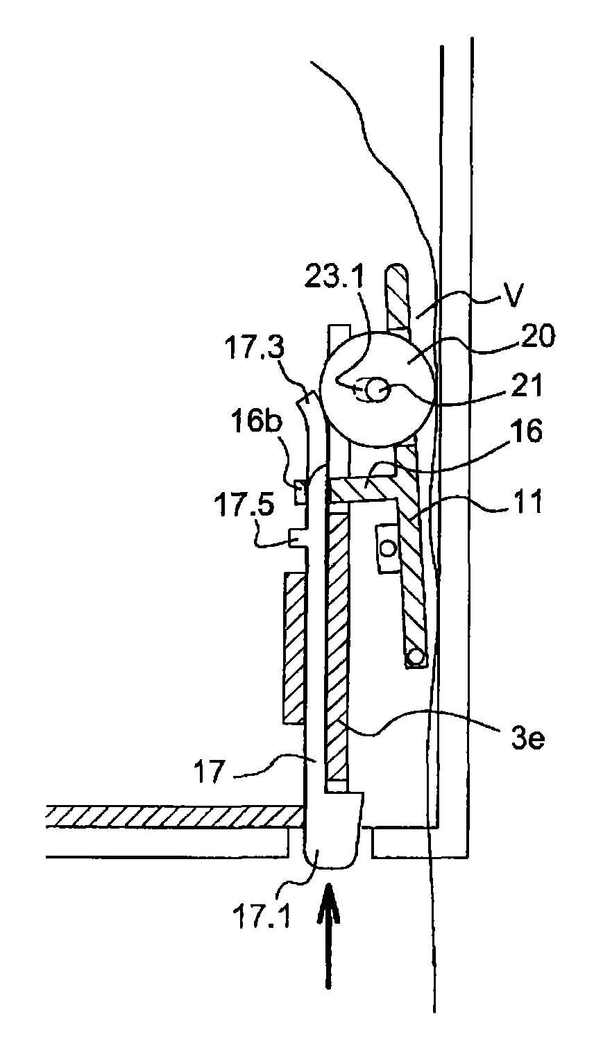
The machine includes a housing receiving an articulated cover closed by raising it and a module which accommodates a pre-cut wound strip of material. The module has a flap located opposite the inner face of the cover and articulated relative to the module, and a device enabling pulling on the end of the strip. The module enables positioning and articulation of the flap, and includes a support plate for the device. The device includes a vertically arranged pusher which slides in a controlled, limited manner relative to a face of the support plate. The pusher has a lower gripping and contact part and an upper end that forms a cam. A roller of the device cooperates with the upper end of the pusher. The pusher cooperates with the flap. The device acts on the flap to ensure its rearward swivelling to allow un-jamming and strip emergence from the machine.

Description

CROSS REFERENCE TO RELATED APPLICATIONS[0001]This application is a national stage filing under section 371 of International Application No. PCT / FR2011 / 052354, filed on Oct. 10, 2011, and published in French on Apr. 26, 2012, as WO 2012 / 052653 and claims priority of French application No. FR 1058449 filed on Oct. 18, 2010, the entire disclosure of these applications being hereby incorporated herein by reference.BACKGROUND ART[0002]The invention relates to the technical field of dispensing machines for wipe materials of the wadding paper type for hand wipe, toilet paper and general-purpose wiping and cleaning applications.[0003]The wipe material may be presented in various configurations which have all been the subject of design work and research carried out by the Applicant who has specialised in dispensing machine technology for roughly 40 years and has filed a very large number of patents.[0004]The wipe material may be wound on a reel and be dispensed by dispensing machines which i...

Claims


Application Information

Patent Timeline
IPC IPC(8): A47K10/34A47K10/36A47K10/32
CPCA47K10/34A47K2010/3233A47K2010/3675A47K10/3656
Inventor GRANGER, MAURICE
Owner GRANGER MAURICE
Learn More