Coil forming apparatus and method

一种线圈、线圈板的技术,应用在线圈形成装置以及领域,能够解决昂贵、系统复杂等问题,达到易于操作和控制、实施方式便宜的效果

Active Publication Date: 2015-07-29
PRIMETALS TECH USA
View PDF6 Cites 1 Cited by
  • Summary
  • Abstract
  • Description
  • Claims
  • Application Information

AI Technical Summary

Problems solved by technology

However, the advantages of this are largely outweighed by the obvious disadvantages, not the least of which is that the systems for supporting and vertically adjusting the two coil plate assemblies and coordinating their movement are too complex and expensive

Method used


Image

  • Coil forming apparatus and method
  • Coil forming apparatus and method
  • Coil forming apparatus and method

Examples


Embodiment Construction

[0018] The components described below as constituting the respective embodiments are intended to be illustrative and not restrictive. Many suitable components and materials described herein that can perform the same or a similar function are intended to be within the scope of embodiments of the invention.

[0019] Embodiments of the present invention will now be described in detail with reference to the accompanying drawings, in which like reference numerals refer to like parts.

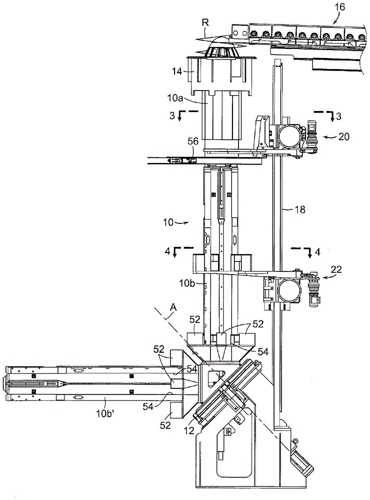
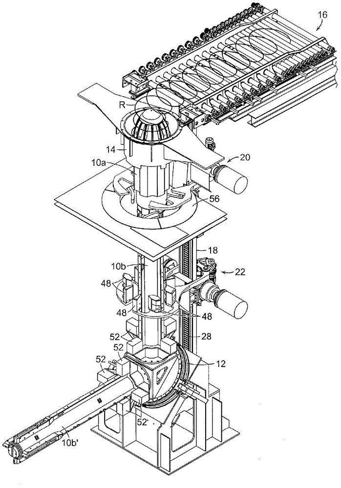
[0020] First refer to figure 1 and figure 2 , a device according to an exemplary embodiment of the invention is shown comprising a vertically arranged mandrel 10 having an upper end 10a (commonly referred to as a "nose cone") detachable from a bottom bar 10b. The mandrel rod 10b and the counter-mandrel rod 10b' are arranged on the base 12 orthogonally. The base is rotatable about axis "A".

[0021] The upper end 10a of the mandrel 10 protrudes upwards into the reforming chamber 14 and is po...


PUM


Abstract

An apparatus is disclosed for receiving a helical formation of rings free falling from the delivery end of a conveyor, and for gathering the rings into a coil. The apparatus comprises a vertically disposed mandrel having an upper end positioned for encirclement by the free falling rings. A vertically disposed support column is positioned adjacent to the mandrel. Upper and lower coil plate assemblies are carried by and vertically adjustable on the support column. A drive system vertically adjusts the coil plate assemblies in a descending manner in which the free falling rings encircling the mandrel are initially accumulated on the upper coil plate assembly before being transferred onto the lower coil plate assembly.

Description

[0001] Cross References to Related Applications [0002] This application claims the benefit of U.S. Provisional Application Serial No. 61 / 731,115, filed November 29, 2012, under 35 U.S.C. § 119(e), the entire contents and substance of which is incorporated herein by reference. technical field [0003] Embodiments of the invention generally relate to a wire rod mill that forms hot rolled product into a series of helical loops that are subjected to controlled cooling while being transported in a stacked pattern on a conveyor. In particular, the present invention relates to an improved apparatus and method for receiving rings as they are free-falling from the discharge end of a conveyor and for gathering the rings into a cylindrical coil. Background technique [0004] In the coil forming apparatus disclosed in U.S. Patent No. 6,073,873 (Shore et al.), support for coils formed from free-falling loops is initially provided by the upper coil plate assembly, and then the coil bein...

Claims


Application Information

Patent Timeline
Patent Type & Authority Applications(China)
IPC IPC(8): B21C47/14B21C47/24
CPCB21C47/245B21C47/14B21C47/242B21C47/04
Inventor 基思·E·菲奥鲁奇克里斯托弗·D·拉舒亚休·T·奥尼尔
Owner PRIMETALS TECH USA
Why Eureka
Try Eureka