Method and machine for transferring packets

Inactive Publication Date: 2006-09-19
GD SPA
8 Cites 2 Cited by

AI-Extracted Technical Summary

Problems solved by technology

As a result, the lead packet contacts the end wall with fairly considerable force capable of damaging the lead packet.
Moreover, a...

Benefits of technology

[0005]It is an object of the present invention to provide a method of transferring packets, designed ...

Abstract

A method and machine for transferring packets, whereby, as a continuous line of packets is fed in a first direction, the first packet in the line is transferred in a second direction perpendicular to the first direction, while the line and the first packet continue travelling in the first direction; the first packet is subsequently conveyed in the second direction along an output path.

Application Domain

Technology Topic

Image

  • Method and machine for transferring packets
  • Method and machine for transferring packets
  • Method and machine for transferring packets

Examples

  • Experimental program(1)

Example

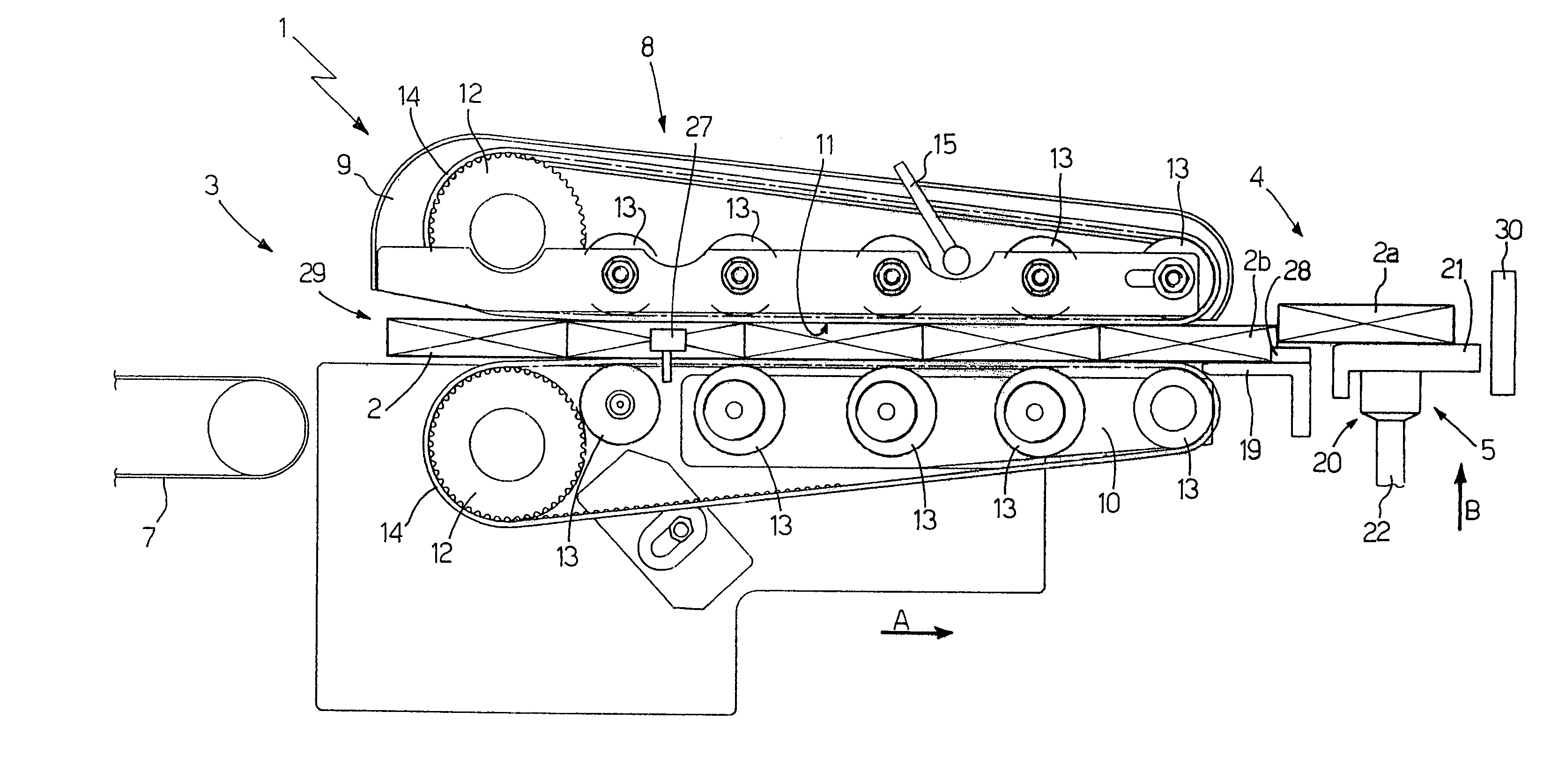
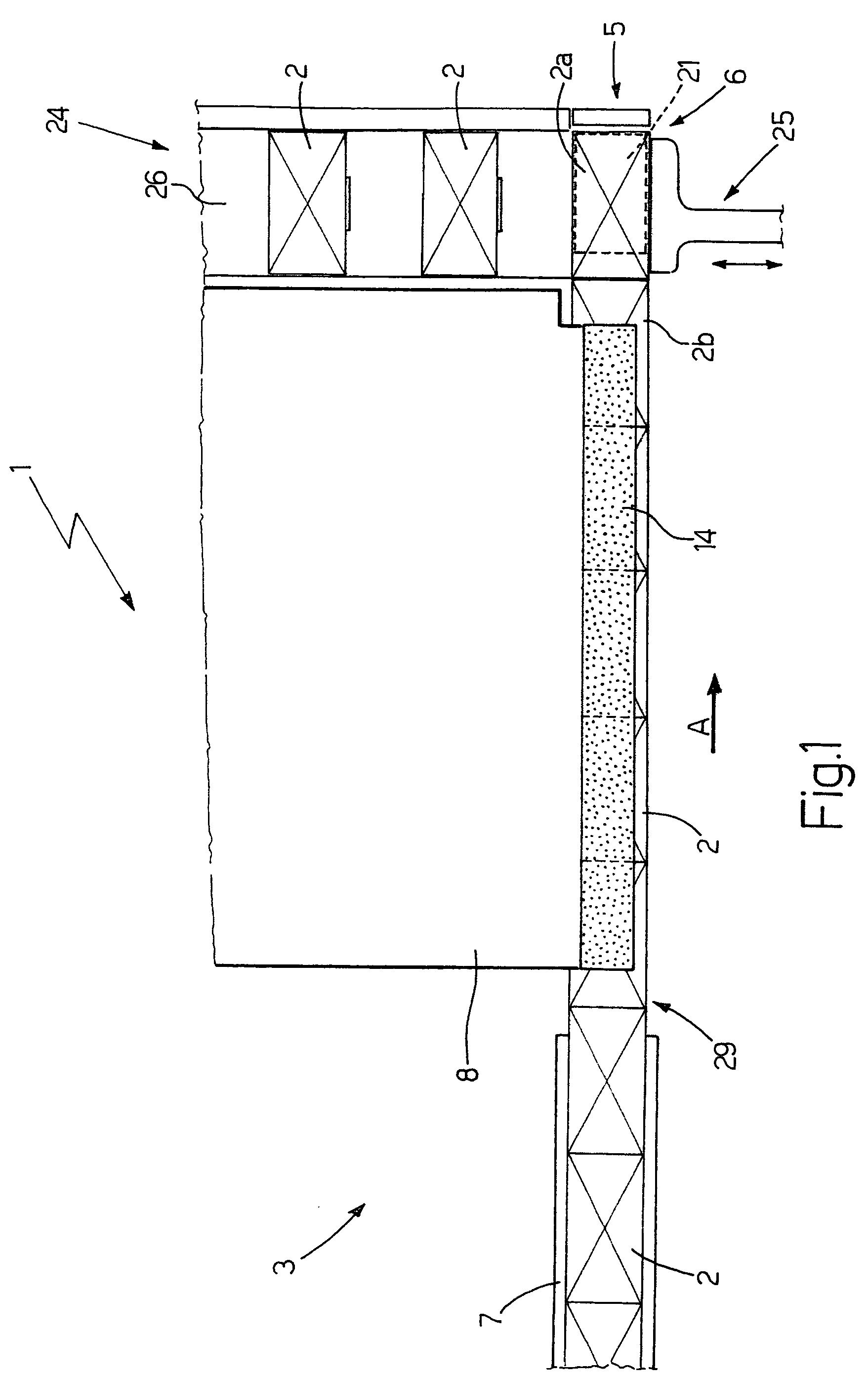
[0014]Number 1 in FIG. 1 indicates as a whole a machine for transferring substantially parallelepiped-shaped packets 2, in particular packets of cigarettes, from a known packing machine not shown.
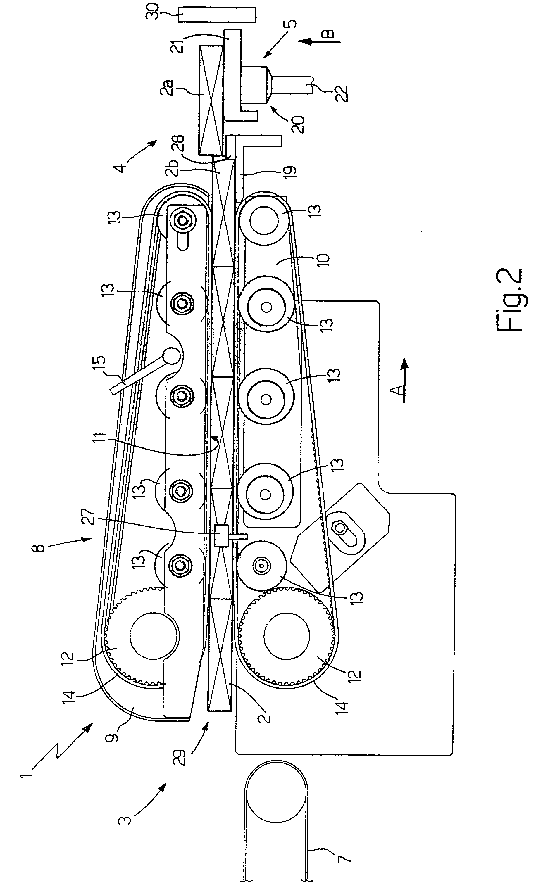
[0015]With reference to FIGS. 1, 2 and 3, machine 1 comprises a feed unit 3 for feeding packets 2 horizontally in a feed direction A to a transfer station 4; and a transfer unit 5 for transferring at least one packet 2a, located at transfer station 4, to an output station 6 in a transfer direction B substantially perpendicular to feed direction A.
[0016]Feed unit 3 comprises a conveyor belt 7 which feeds packets 2 to a further two-belt conveyor 8. Conveyor 8 feeds the packets to transfer station 4, is located downstream from conveyor belt 7, and comprises a top conveying assembly 9 and a bottom conveying assembly 10 defining, in between, a feed channel 11 for packets 2.
[0017]Each conveying assembly 9, 10 comprises a drive pulley 12, and a number of—in the example shown, five—idle pulleys 13; and the respective pulleys 12 and 13 of the two assemblies are located on opposite sides of channel 11.
[0018]Each conveying assembly 9, 10 comprises a belt 14 looped about relative pulleys 12 and 13 and which engages the walls of packets 2 to feed packets 2 in feed direction A.
[0019]Conveying assembly 9 has a known guide device (not shown) for raising conveying assembly 9 to adjust the distance between it and conveying assembly 10; and a known locking device (not shown) operated by a lever 15 to lock conveying assembly 9 in a given position.
[0020]Conveyor 8 comprises an electric motor 16 for driving pulleys 12 by means of a belt 17 (shown schematically in FIG. 4) which is kept taut by a tension pulley 18.
[0021]Finally, conveyor 8 comprises a slide plate 19 located immediately downstream from conveying assembly 10 and having a top slide surface substantially coplanar with a bottom surface of channel 11.
[0022]Transfer unit 5 comprises a lifter 20, in turn comprising a lift head 21; and a rod 22, one end of which is integral with lift head 21, and the other end of which is connected by a cam follower to a cam 23 rotated about a respective axis by a motor M (FIG. 4). As can be seen, the length, in feed direction A, of lift head 21 is shorter than the length, in feed direction A, of the wall of packet 2a.
[0023]In actual use, lift head 21 intercepts packet 2a at transfer station 4, and moves upwards in transfer direction B to transfer it to output station 6.
[0024]Machine 1 also comprises a conveying unit 24 located downstream from transfer unit 5 to convey packets 2a along an output path from output station 6. Unit 24 comprises a push device 25 for feeding packet 2a at output station 6 onto a belt conveyor 26.
[0025]Finally, machine 1 comprises a sensor 27 for detecting any gaps between packets 2 inside channel 11; and a sensor 28 for detecting the position of a second packet 2b behind packet 2a in feed direction A. Sensors 27 and 28 are connected to a known control unit (not shown) which controls the speed of motor 16 as a function of the position of lift head 21. The speed of motor 16 is also adjusted on the basis of the position of packet 2b determined by sensor 28. More specifically, if packet 2b is ahead with respect to a given predetermined position, motor 16 is slowed down accordingly. When sensor 27 detects, in use, a gap between packets 2 in channel 11, the known control unit (not shown) arrests motor 16 and motor M.
[0026]In use, the individual incoming packets from the known packing machine (not shown) are fed by conveyor belt 7 to conveyor 8 at a constant speed greater than the maximum travelling speed of conveyor 8. Upstream from conveyor 8 and inside channel 11, a continuous line 29 of packets 2 is formed, and of which packet 2a is the lead packet in feed direction A. On the basis of the length of line 29, which is determined by known sensors (not shown), the known control unit (not shown) adjusts the speed of motor M of transfer unit 5 so that the longer line 29 is, the greater the speed of motor M of transfer unit 5 is.
[0027]The line 29 of packets 2 inside channel 11 is fed by conveyor 8 to transfer station 4 in feed direction A. When packet 2a is positioned correctly at transfer station 4 so as to be partly supported by lift head 21, head 21 is moved vertically upwards in transfer direction B. As packet 2a is being raised, line 29 continues moving so that packet 2b pushes packet 2a in feed direction A until packet 2a reaches output station 6 and is separated completely from line 29.
[0028]It should be stressed that the movements of lift head 21 and the speed at which conveyor 8 conveys line 29 are so regulated that packet 2a never comes into contact with an end wall 30 located at the end of transfer station 4 in feed direction A.
[0029]At this point, push device 25 is operated so that packet 2a at the output station is fed along the output path defined at least partly by conveyor 26. Lift head 21 moves back and forth in transfer direction B so as to move down after feeding packet 2a to output station 6.
[0030]In this connection, it should be stressed that the movements of lift head 21 and the travelling speed of line 29 are so regulated that head 21 does not interfere with the travel of line 29 inside transfer station 4. More specifically, the travelling speed of line 29 in feed direction A varies as a function of the position of lift head 21, and therefore in a definite manner with time.
[0031]The FIG. 5 graph shows, purely by way of example, the travelling speed of line 29 (y axis) as a function of the machine angle of transfer unit 5 (x axis). In FIG. 5, portion C-D represents the downward movement of lift head 21, point E represents the instant in which head 21 begins moving upwards, and portion E-C represents the upward movement of head 21 (i.e. transfer of packet 2a in transfer direction B).
[0032]The travelling speed of line 29 along portion C-D is relatively low (in particular, less than or equal to the speed along portion D-C) and reaches a maximum when lift head 21 is positioned beneath transfer station 4. Head 21 therefore has enough time to move downwards without coming into contact with line 29, and without interfering with the movement of line 29 in feed direction A. The travelling speed of line 29 typically slows down along portion E-C.
[0033]It should be pointed out that the travelling speed of line 29 in feed direction A is also preferably varied as a function of the position of packet 2b as head 21 begins moving upwards. For which purpose, the real position of packet 2b is determined the instant packet 2a begins to be lifted, and is compared with an ideal theoretical position. When packet 2b falls short of the ideal position, the travelling speed is increased slightly with respect to that shown by way of example in FIG. 5; and, conversely, if packet 2b is ahead of the ideal position, the travelling speed is reduced slightly with respect to that shown by way of example in FIG. 5.

PUM

no PUM

Description & Claims & Application Information

We can also present the details of the Description, Claims and Application information to help users get a comprehensive understanding of the technical details of the patent, such as background art, summary of invention, brief description of drawings, description of embodiments, and other original content. On the other hand, users can also determine the specific scope of protection of the technology through the list of claims; as well as understand the changes in the life cycle of the technology with the presentation of the patent timeline. Login to view more.

Similar technology patents

Appliance for distributing a precut wiping material that is rolled up or folded in a Z shape

InactiveUS9408505B2Cheap to implementEffective interventionFilament handlingDomestic applicationsSkin flapCam
Owner:GRANGER MAURICE

Method of folding a sheet of packing material about a group of cigarettes

InactiveUS20090320414A1Cheap to implementPackaging cigaretteWrapper folding/bending apparatusEngineeringMechanical engineering
Owner:GD SPA

Classification and recommendation of technical efficacy words

  • Cheap to implement

Method of raising a building

Owner:SO L E S SOC LAVORI EDILI E SERBATOI +1

Method of controlling an automatic production/packing machine

InactiveUS20090044491A1Cheap to implementCapsCapping machinery safety/controlManufacturing engineeringControl unit
Owner:GD SPA

Cigarette packing machine for producing rigid hinged-lid packets

InactiveUS20060254212A1Cheap to implementPackaging cigaretteWrapper folding/bending apparatusCigarette packEngineering
Owner:GD SPA
Why Eureka
Try Eureka