
Front-end circuit for improved antenna performance

a front-end circuit and antenna technology, applied in the direction of antennas, antenna details, antenna earthing switches, etc., can solve the problem that the first antenna cannot transmit or receive radio frequency signals, and achieve the effect of improving antenna performan

Active Publication Date: 2014-05-06
SNAPTRACK
View PDF19 Cites 0 Cited by
  • Summary
  • Abstract
  • Description
  • Claims
  • Application Information

AI Technical Summary

Benefits of technology

[0006]In one aspect, the present invention provides a front-end circuit for use with at least two different antennas in a respective mobile communication device with an improved antenna performance.
[0009]Modern mobile communication devices that are operable in different frequency bands and / or provide multi-mode operation and that suffer from detrimental mutual interaction of different antennas comprise already intrinsically means that can be used for reducing the detrimental interaction. The second antenna that causes interaction can be utilized to reduce or prevent the primary interaction. The presented method for preventing or reducing unwanted interaction between two antennas, thus, is relatively cheap and simple to implement.
[0014]The filter has passive elements or a plurality of passive elements that may work as a bandpass filter, a high-pass filter or a low-pass filter for one of the frequency bands of the mobile communication device. If the active antenna operates in a frequency band that is not the operative frequency band of the filter then the filter may not show a resonating behavior that generally is characterized by “zero” or “infinite” impedance (i.e., resonance and anti-resonance respectively). Thus, the filter may provide an antenna termination circuit for the inactive antenna that has an impedance that does not vary much with frequency and thus is well suited to provide a stable termination circuit.
[0017]Filters like bandpass filters that work with acoustic waves (i.e., surface acoustic waves, SAWs; bulk acoustic waves, BAWs) usually comprise electrodes being arranged on one or two surfaces of a piezoelectric substrate. The impedance behavior of a bandpass filter working with acoustic waves within the active frequency range, i.e., within the bandpass of the filter, is complex due to the electroacoustic interactions with radio frequency signals. However, in a frequency range that does not overlap with the passband of a bandpass filter, the respective filter acts as an impedance component, for example, as a capacitive component due to the electrode structure that act as electrodes of a capacitive element. As such filters are usually contained in front-end circuits for filtering radio frequency signals, the use of such filters within antenna termination circuits enables enhancing the respective antenna performance of the active antenna without the need for further integration of additional impedance components.
[0020]A front-end circuit that enables choosing the termination state of the inactive antenna further leads to an improved front-end circuit and to an improved communication device as the degree of freedom of the termination state is increased.
[0022]It may be preferred that the termination impedance may have an absolute value that is as low as possible. Although ground may be regarded as an electromagnetic potential of zero impedance, respective electric connections usually have parasitic capacitances, parasitic and finite resistance values. By simultaneously connecting the inactive antenna port to at least two short terminated connections, the resistance between the antenna port and ground is reduced.

Problems solved by technology

However, the first antenna may not be in use, meaning that the first antenna may not transmit or receive radio frequency signals.

Method used


Image

  • Front-end circuit for improved antenna performance
  • Front-end circuit for improved antenna performance
  • Front-end circuit for improved antenna performance

Examples


Embodiment Construction

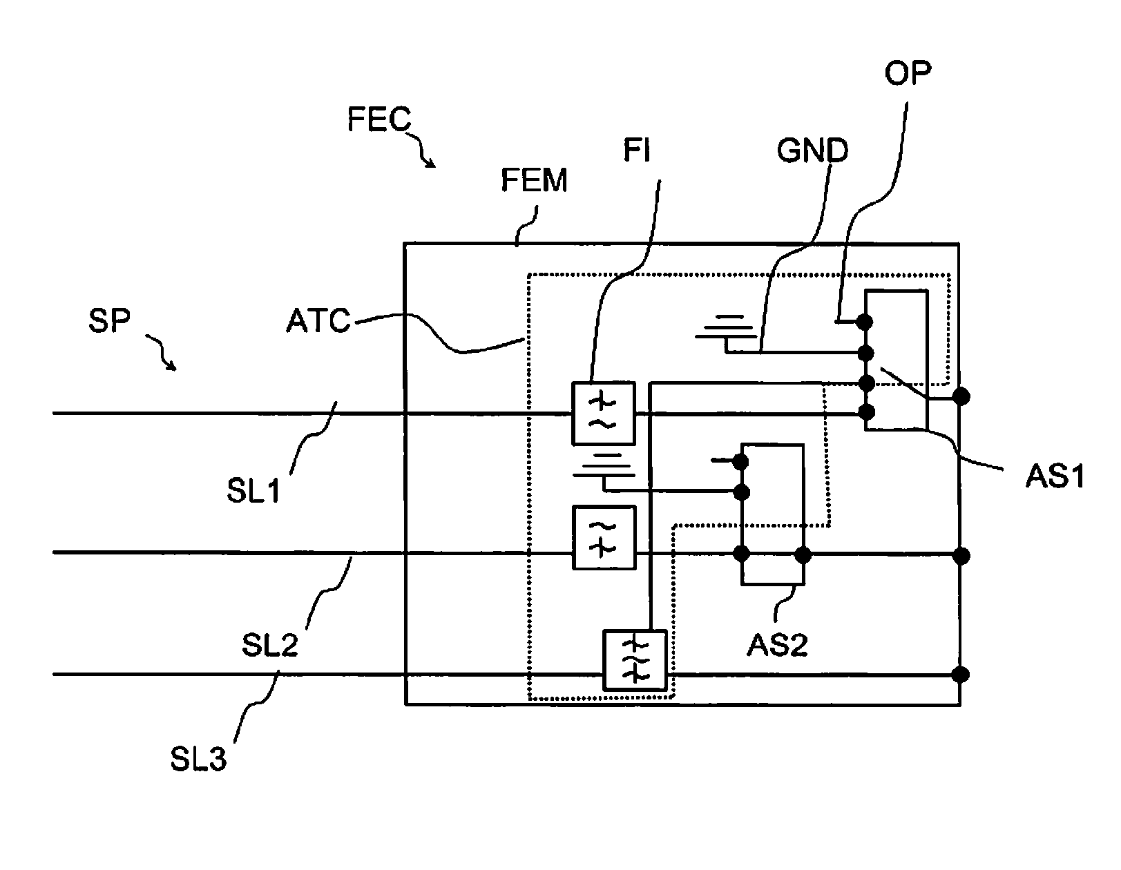
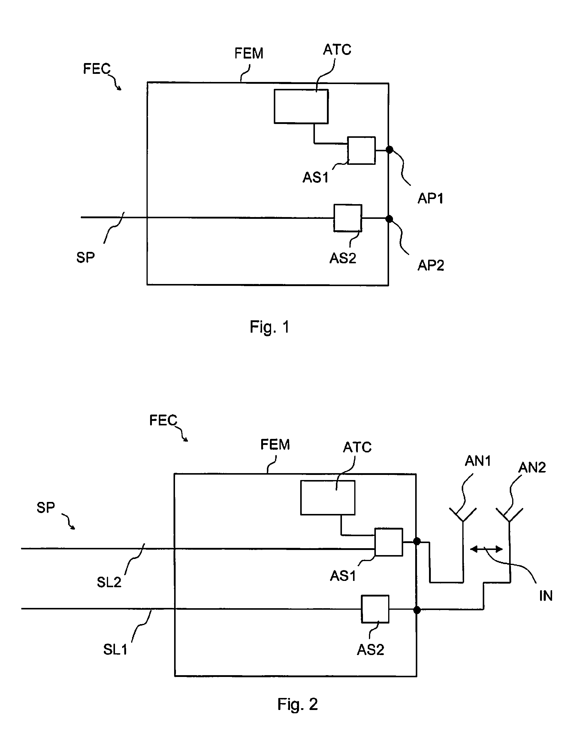
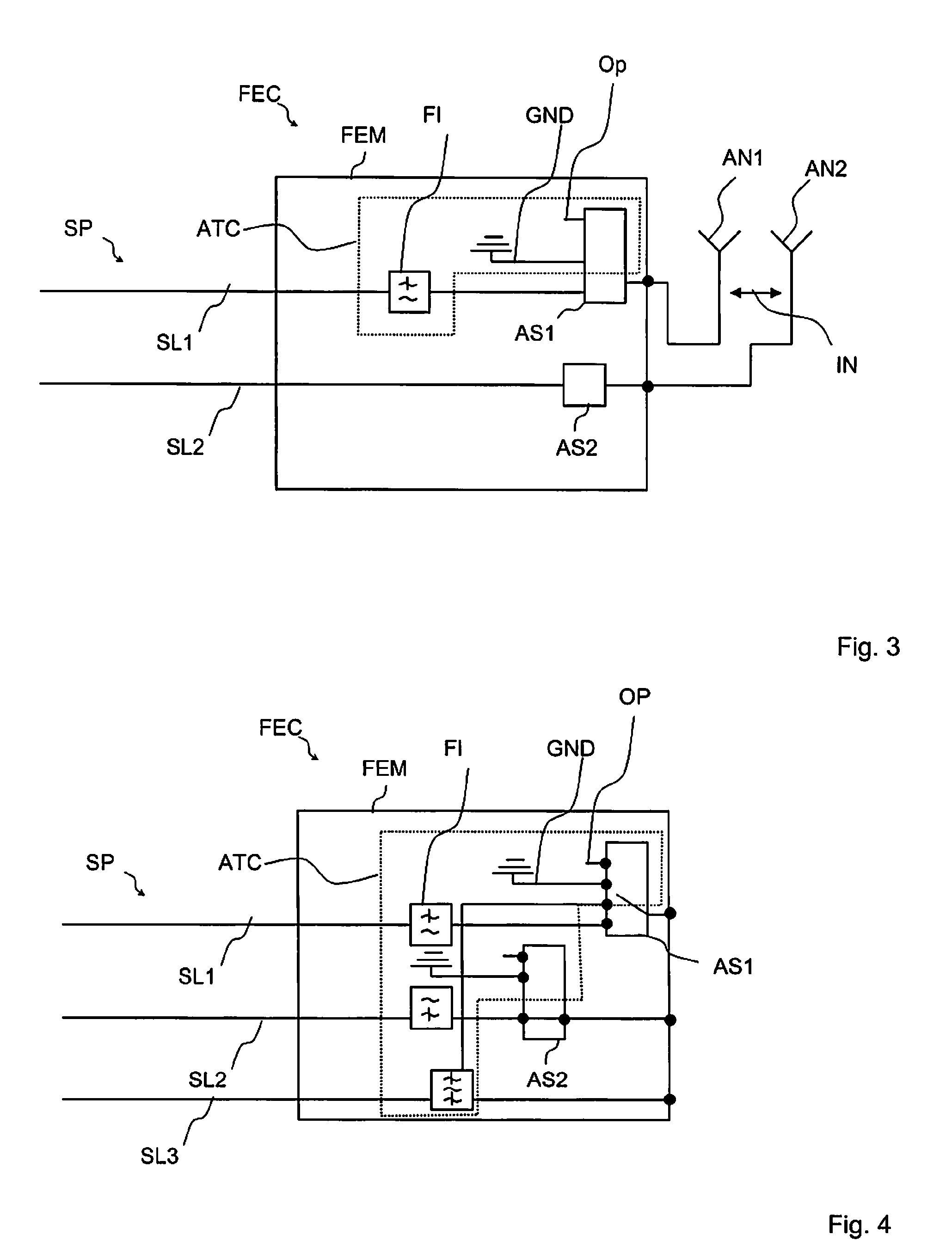
[0063]FIG. 1 illustrates circuitry according to an embodiment of the invention. A front-end circuit FEC is comprised within a front-end module FEM. The front-end circuit FEC comprises an antenna termination circuit ATC, a first antenna switch AS1 and a second antenna switch AS2. The first antenna switch AS1 electrically connects the antenna termination circuit ATC with a first antenna port AP1. The second antenna switch AS2 electrically connects a signal path SP with a second antenna port AP2.

[0064]The first antenna port AP1 may be connected with a first antenna and the second antenna port AP2 may be connected with a second antenna. When the second antenna is in use and receives or transmits radio frequency signals via the signal path SP, the first antenna is inactive and the first antenna switch AS1 electrically connects the first antenna with the antenna termination circuit ATC in order to reduce detrimental electromagnetic interaction between the first and the second antenna.

[006...


PUM


Abstract

A front-end circuit includes a signal path and a first antenna port. A first antenna switch is electrically connected to the first antenna port. A second antenna port is electrically connectable or connected to the signal path. An antenna termination circuit is electrically connected to the first antenna switch. The antenna termination includes an impedance element. The first antenna switch electrically connects the first antenna port to the antenna termination circuit when the signal path is electrically connected to the second antenna port.

Description

[0001]This application is a continuation of co-pending International Application No. PCT / EP2009 / 064094, filed Oct. 26, 2009, which designated the United States and was published in English, which application is incorporated herein by reference.TECHNICAL FIELD[0002]The present invention refers to a front-end circuit that provides mobile communication devices, such as mobile phones, with an improved antenna performance and methods for driving such a front-end circuit.BACKGROUND[0003]Mobile communication devices generally utilize radio frequency signals for communication with remote devices such as other mobile communication devices or base stations. Modern mobile communication devices have to fulfill many requirements. Among these are multi-band operations and multi-mode operations. Modern mobile communication devices usually are able to transmit and / or receive radio frequency signals towards or from a plurality of transmitters or receivers, respectively. Especially communication devi...

Claims


Application Information

Patent Timeline
Patent Type & Authority Patents(United States)
IPC IPC(8): H01Q3/24H01Q1/50H01Q21/00
CPCH01Q1/242H01Q1/521
Inventor TIKKA, PASIVALTONEN, JARMO
Owner SNAPTRACK
Learn More