Multipart case wireless communications device with multiple groundplane connectors

a wireless communication and connector technology, applied in the direction of antenna earthing, antenna monopole, resonant antenna, etc., can solve the problems of poor antenna performance, unintentional generation of current through the transceiving device, poor antenna performance, etc., to optimize the ground current flow, optimize the antenna performance, and maximize the distance between the antenna and the interface

Inactive Publication Date: 2007-05-31
KYOCERA CORP
View PDF9 Cites 47 Cited by
  • Summary
  • Abstract
  • Description
  • Claims
  • Application Information

AI Technical Summary

Benefits of technology

[0008] A multipart electrical interface design is disclosed that optimizes ground current flow being housing sections at antenna frequencies. In one embodiment, multiple interfaces between case sections is provided and the distance between the antenna and the interfaces is maximized and the frequency response of the electrical interfaces are tuned. As a result, antenna performance is optimized and receiver degradation is minimized.

Problems solved by technology

An antenna that depends heavily on the ground plane, such as a patch antenna, planar inverted-F antenna (PIFA), or folded monopole, may perform poorly when a grounded metal is near the antenna in some configurations.
One measure of poor antenna performance is the amount of current unintentionally generated through a transceiving device, typically as surface currents, as opposed to amount of energy radiated into the intended transmission medium (i.e., air).
From the receiver perspective, poor antenna performance is associated with degraded sensitivity due to noisy grounds.
From either point of view, poor performance can be associated with radio frequency (RF) ground currents.
The above-mentioned ground issues are compounded with the use of multipart type cell phone cases.
These long thin signal wires may unintentionally act as antennas, interfering with the intended antennas and degrading the receiver performance.
While this brute-force approach does shield the connector signal lines, other problems may be introduced.
Using a cell phone as an example, the shielded flex connector may cause a desired upward-pointing radiation pattern in the PCS band to point in an alternate, less desirable direction.

Method used


Image

  • Multipart case wireless communications device with multiple groundplane connectors
  • Multipart case wireless communications device with multiple groundplane connectors
  • Multipart case wireless communications device with multiple groundplane connectors

Examples


Embodiment Construction

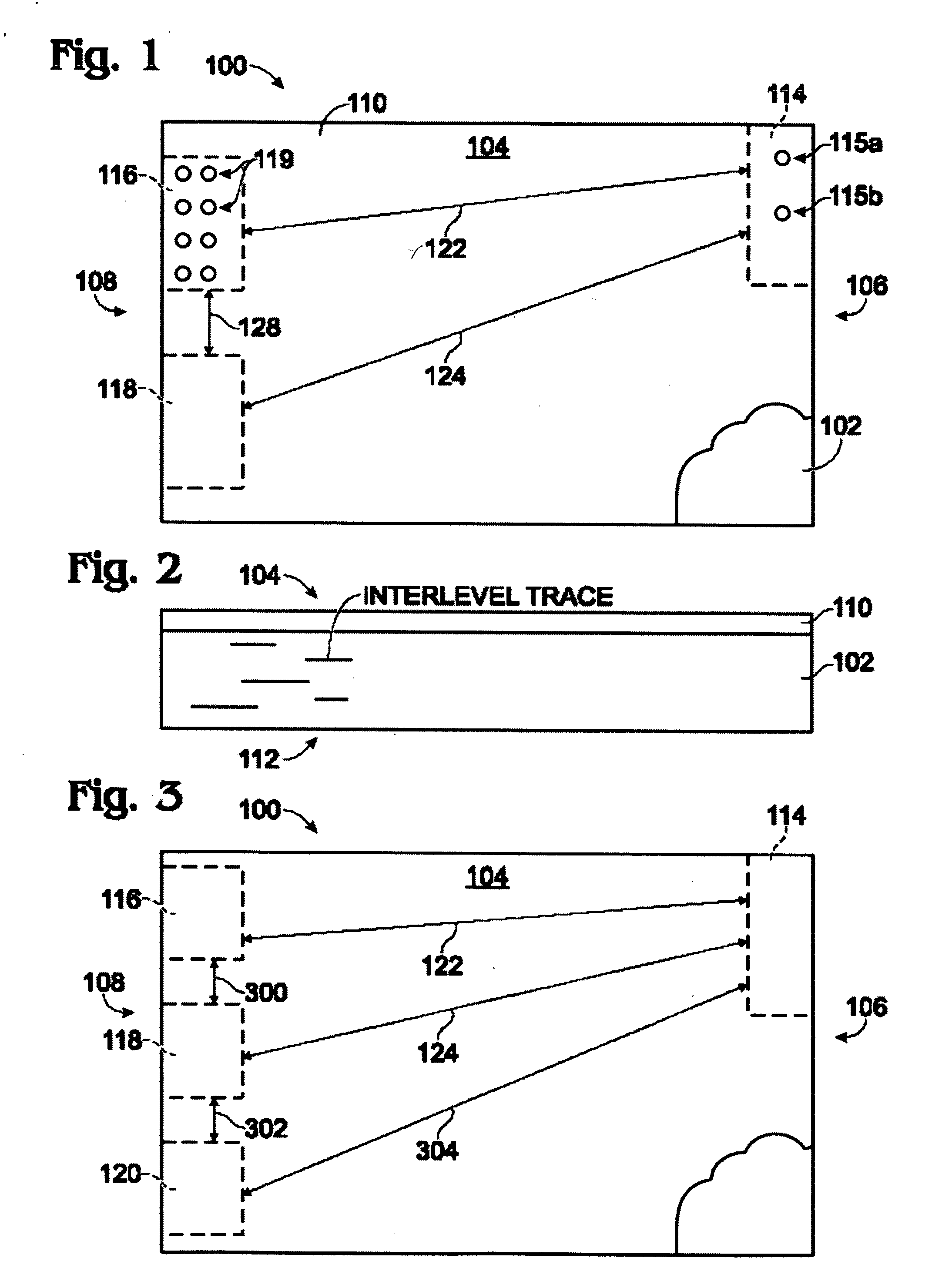
[0024]FIG. 1 is a plan view of a printed circuit board (PCB) associated with a wireless communication device with a multipart case according to an embodiment of the invention. The PCB 100 comprises a sheet of dielectric 102 with a planar surface 104 having a first end 106 and an opposite second end 108. Although the board is shown as having a rectangular shape for simplicity, it should be understood that the invention is not limited to any particular board shape.

[0025]FIG. 2 is a partial cross-sectional view of the PCB 100 of FIG. 1. Viewing both FIGS. 1 and 2, a conductive groundplane layer 110 is shown overlying the dielectric surface 104. For simplicity, the groundplane layer 110 is shown as the top (surface) layer. However, it should be understood that in other aspects of the invention not shown, that the groundplane layer 110 may be an internal layer of a multilayer board, formed on the PCB bottom surface 112, or formed on multiple layers of a multilayer board. Likewise, signa...


PUM


Abstract

A wireless communication device is provided with a multipart case, having electrical interfaces that encourage the flow of radiation frequency ground current between case sections. The multipart case has a first planar groundplane section and a second planar groundplane section. For example, the multipart case design may be a slider, double slider, multiple hinge, flip, or swivel case. The second planar groundplane is substantially coplanar with the first groundplane in a case open position, and substantially bi-planar with the first groundplane in a case closed position. The wireless device also includes an antenna located adjacent the second groundplane section first end. A first and a second interface electrically connect the first groundplane section to the second groundplane section second end (the end opposite the antenna).

Description

RELATED APPLICATIONS [0001] This application is a continuation-in-part of application Ser. No. 10 / 965,169, filed Oct. 13, 2004, and of application Ser. No. 11 / 215,211, filed Aug. 29, 2005, the disclosures of which are incorporated herein by reference.FIELD OF THE INVENTION [0002] This invention generally relates to wireless communications and, more particularly, to a wireless device with electrical interfaces between a multipart case that optimize the conduction of ground currents at antenna radiation frequencies. BACKGROUND OF THE INVENTION [0003] Consumers are demanding smaller and feature-rich wireless communication devices, such as cellular (cell) telephones. A smaller cell phone with more functions and features can be produced with two housing portions. One such multipart configuration is a flip phone. A flip phone opens up like a clamshell. Other configurations are sliding phones and swivel phones. In a sliding phone, one portion of the cell phone housing slides relative to th...

Claims


Application Information

Patent Timeline
Patent Type & Authority Applications(United States)
IPC IPC(8): H01Q1/24
CPCH01Q1/243H01Q1/48H01Q9/0421H01Q1/24H01Q9/04
Inventor JENWATANAVET, JATUPUMPOILASNE, GREGORYFABREGA-SANCHEZ, JORGEPATHAK, VANEETLE, JOE
Owner KYOCERA CORP
Why Eureka
Try Eureka