Spring carrier

Inactive Publication Date: 2005-02-22
THYSSENKRUPP AUTOMOTIVE
View PDF10 Cites 96 Cited by
  • Summary
  • Abstract
  • Description
  • Claims
  • Application Information

AI Technical Summary

Benefits of technology

The object of the present invention is accordingly a supporting column in the form of a generic upright spring improved to the extent that the distan

Problems solved by technology

Furthermore, when employed with conventional combinations of telescoping leg and dashpot, these devices need not be spec

Method used


Image

  • Spring carrier
  • Spring carrier
  • Spring carrier

Examples


Embodiment Construction

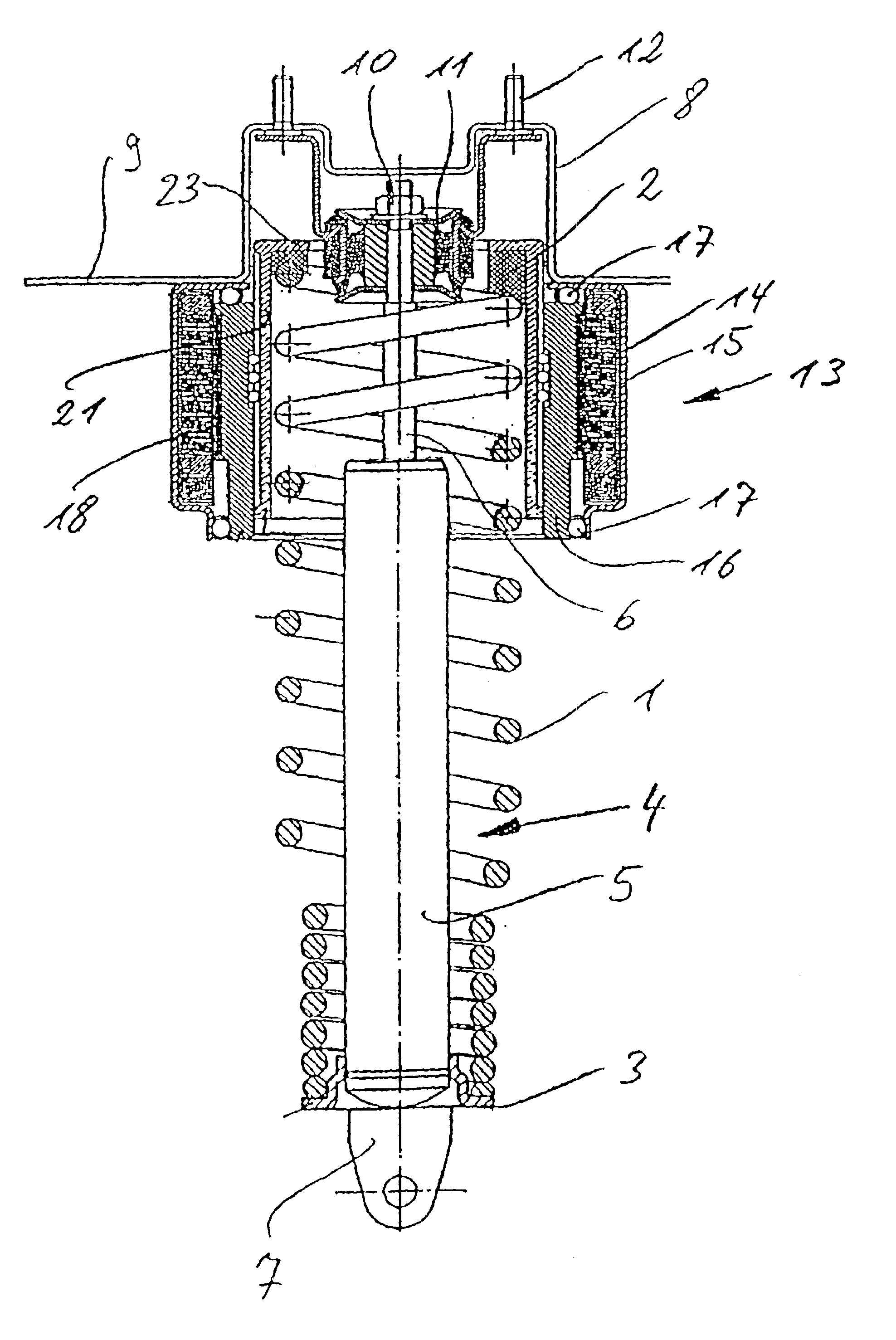
The supporting column depicted in FIG. 1 comprises a helical spring 1. One end of spring 1 rests against a cap 2 and the other end against another cap 3. A dashpot 4 is accommodated inside spring 1 along its central axis. Dashpot 4 comprises a cylinder and a piston rod 6. Piston rod 6 travels in and out of cylinder 5. Cap 3 is secured to the lower end of cylinder 5 by a groove and tensioning ring. The overall supporting column is connected to the wheel suspension by a flange 7.

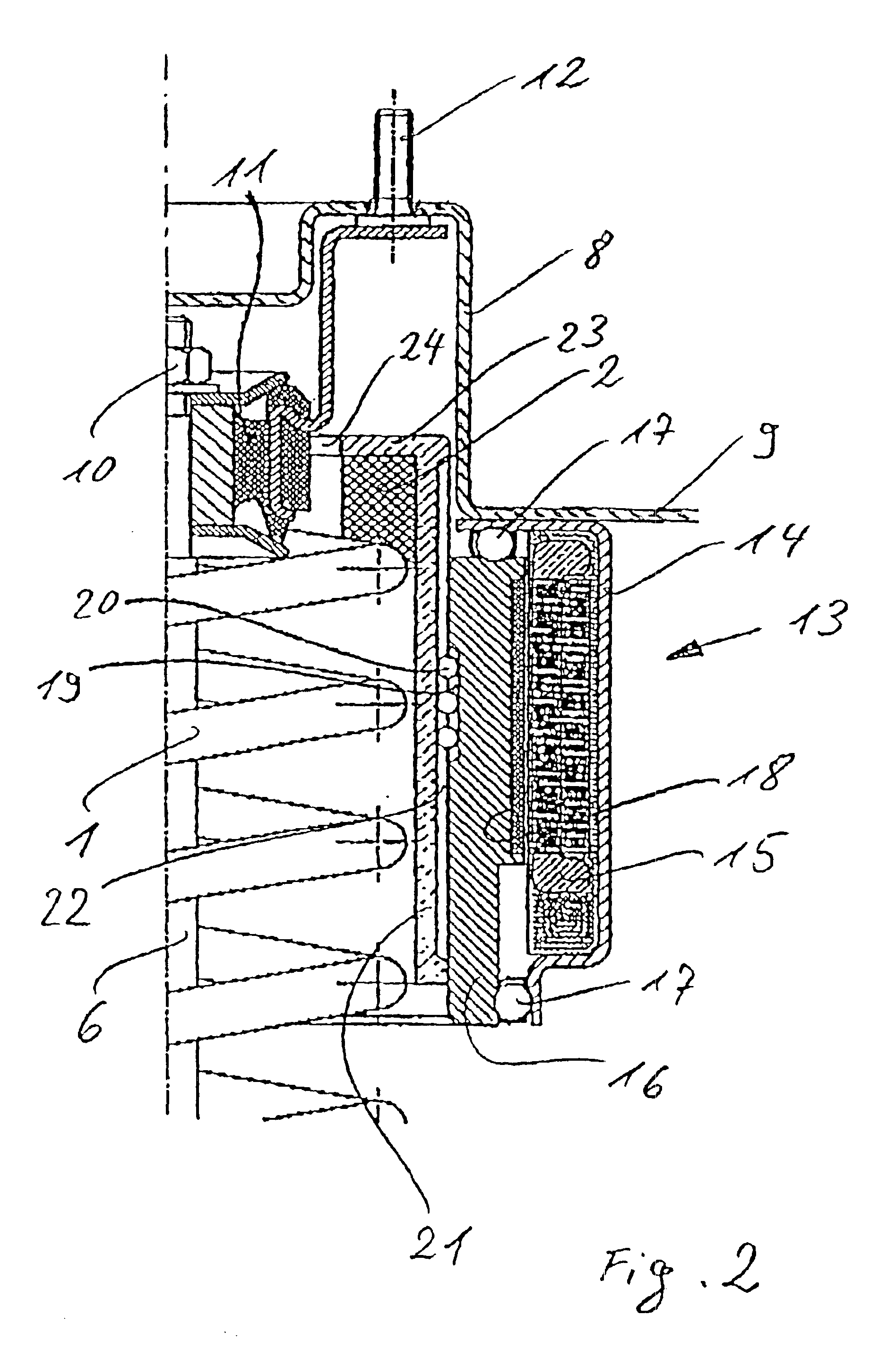
Half of the upper part of the joint between piston rod 6 and spring 1 and the axial adjuster or chassis is depicted in larger scale section in FIG. 2. Piston rod 6 is conventionally attached to an arbor-like dome 8 on one component 9 of the chassis. Piston rod 6 is for this purpose is fastened by a nut 10 to a flexible and resilient connector half 11. Connector half 11 itself is fastened to dome 8 by screws 12.

The outer housing 14 of an axial adjuster 13 rests against the bottom of component 9 and is attached ...


PUM


Abstract

The invention relates to a spring carrier for the chassis of a motor vehicle. Said carrier is used to support a coil spring (1) which is braced between two spring plates (2, 3). At least one of said spring plates (2) can be axially adjusted by means of a drive unit comprising a gearbox and an electric motor. Preferably, at least one part of the piston rod (6) and/or the shock-absorber tube (5) of a shock-absorber or a suspension strut is arranged inside the coil spring (1). The aim of the invention is to develop one such spring carrier in such a way that the distance between the upper spring end and the vehicle body can be kept small in a cost-effective manner. To this end, the electric motor is embodied in the form of a ring motor having an external stator (15) and an internal rotor (16) which comprises a displacement nut on its inner side, said displacement nut axially displacing a spring plate carrier (21) connected to the spring plate (2) and externally embodied as a threaded spindle.

Description

BACKGROUND OF THE INVENTIONThe present invention concerns a supporting column in the form of a spring with at least one spring-end cap that can be displaced toward the wheel or toward the chassis of a vehicle.Such axially adjustable supporting columns are employed in vehicles with chassis that are intended to be elevated to varying levels above the ground. This feature can be desirable for example once a vehicle has been loaded and the intrusion of its rear suspension must be compensated. Such supporting columns, however, are also employed in on-and-off road vehicles to increase above ground clearance in rough terrains. Furthermore, these supporting columns can be employed in busses that kneel toward the curb at bus stops. Finally, Dynamic rocking and rolling on the part of the chassis can also be eliminated, enabling a level orientation independent of the road surface.A supporting column of this genus is known from German 19 510 032 A1. It has a drawback in that it requires a lot o...

Claims


Application Information

Patent Timeline
IPC IPC(8): B60G17/02B60G15/06F16F9/32F16F9/46
CPCB60G17/021B60G2204/124B60G2500/30B60G2500/20B60G2204/419
Inventor LOSER, FRIEDRICHELLMANN, SIEGFRIED
Owner THYSSENKRUPP AUTOMOTIVE
Why Eureka
Try Eureka