Method of creating a zonal isolation in an underground wellbore

a wellbore and zone isolation technology, applied in the direction of drinking water installation, borehole/well accessories, construction, etc., can solve the problems of high local stress and the inability of the packer to form an effective seal, and achieve the effect of decreasing the permeability of the matrix of packed granular materials and increasing the packing density

Inactive Publication Date: 2006-06-15
SHELL OIL CO
View PDF12 Cites 100 Cited by
  • Summary
  • Abstract
  • Description
  • Claims
  • Application Information

AI Technical Summary

Benefits of technology

[0034] The ends of the centralizer blades can be connected at axially spaced locations to the outer surface of a radially expandable slurry injection tubing, such that the centralizer blades are arranged in a substantially stretched position around the tubing before expansion of the tubing and that the distance between the ends of the stabilizer blades is decreased as a result of the axial shortening of the tubing during the expansion process, whereby the centralizer blades are induced to radially expand within the annulus surrounding the fluid injection tubing.
[0045] The slurry injection tubing may be tapered in the region between the expandable screen assembly and the target zone, such that the velocity of the slurry in the annular space is reduced when the slurry flows from the target zone towards the screen assembly.
[0049] In a particular embodiment the slurry injection tubing is radially expanded after inserting a matrix of packed granular material in the annulus between the slurry injection tubing and the wellbore, thereby increasing the packing density and decreasing the permeability of the matrix of packed granular material.

Problems solved by technology

With inflatable packers, the inflation pressure causes high local stress.
When a lower target zone is to be fractured by applying high pressure, it can thus happen that undesirable fracturing occurs adjacent to the location of the packer, which means that the packer does not form an effective seal anymore.

Method used


Image

  • Method of creating a zonal isolation in an underground wellbore
  • Method of creating a zonal isolation in an underground wellbore
  • Method of creating a zonal isolation in an underground wellbore

Examples


Embodiment Construction

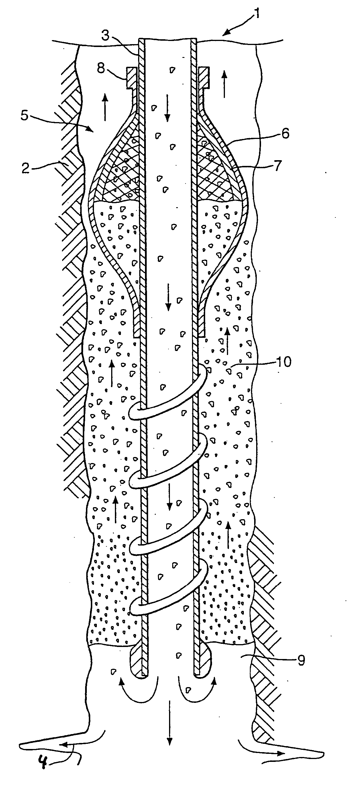
[0082]FIG. 1 depicts a wellbore 1 which traverses an underground earth formation 2. The wellbore 1 may e.g. be used for transport of crude oil and / or natural gas to surface, for circulation of water through fractures in a hot formation for generation of steam and recovery of geothermal energy, for waste injection, for gas storage, and / or as an observation well.

[0083] A slurry injection tubing 3 is suspended from a wellhead at surface (not shown) in the wellbore 1 above a target zone 4 of the wellbore 1, from which target zone the formation 2 is to be fractured or stimulated or where a treatment, etching or disposed fluid is to be injected into the formation 2.

[0084] A particle accumulation means in the form of an expandable screen assembly 5 is arranged around the slurry injection tubing 3, which assembly comprises an expandable bow-spring centralizer assembly 6 to which a permeable barrier layer 7 is attached. The lower ends of the bow spring centralizers 6 are connected to the o...


PUM


Abstract

A method of creating a zonal isolation above a target zone in an underground wellbore comprises: inserting a slurry injection tubing into the wellbore; arranging within an annular space surrounding said tubing an particle accumulation means, such as an expandable screen or an area where the slurry velocity is reduced; and pumping a slurry comprising a carrier fluid and granular material down via the slurry injection tubing and the target zone and then up into the annular space, such that at least some granular material accumulates and forms an elongate zonal isolation in the annular space between the target zone and the particle accumulation means, which zonal isolation is removable and exerts a limited radial force to the surrounding formation, thereby reducing the risk of formation damage.

Description

FIELD OF INVENTION [0001] The invention relates to a method of creating a zonal isolation in an underground wellbore. BACKGROUND OF THE INVENTION [0002] It is common practice to create a zonal isolation in an underground wellbore by inserting an inflatable elastomeric plug or packer in the wellbore. [0003] If the wellbore is an uncased section of an underground borehole then the expanded plug or packer may exert a high radial force on the surrounding underground formation, thereby lowering the compressive hoop stresses in the formation such that fractures may be initiated in the formation adjacent to the plug or packer. [0004] It is known from U.S. Pat. No. 5,623,993 to insert an expandable packer in a wellbore such that the impact on the compressive hoop stresses in the surrounding formation is limited. The packer is equipped with a water drainage conduit and granular material is deposited on top of the packer so that water will drain down through the matrix of granular material, t...

Claims


Application Information

Patent Timeline
Patent Type & Authority Applications(United States)
IPC IPC(8): E21B33/00E21B43/26E21B33/134E21B33/136E21B43/04E21B43/10
CPCE21B33/134E21B33/136E21B43/04E21B43/103E21B43/108
Inventor BLOESS, ANDREASBOSMA, MARTIN GERARD RENECORNELISSEN, ERIK KERSTGUNNINGHAM, MICHAEL CASPARKENTER, CORNELIS JANWORRALL, ROBERT NICHOLAS
Owner SHELL OIL CO
Why Eureka
Try Eureka