Apparatus and method for generating an overview image of a plurality of images using a reference plane

a reference plane and image technology, applied in the field of image processing, can solve the problems of scale and relative distance distortion, multiple image types, and image transformation performed, and achieve the effects of reducing errors caused by considering reference points at largely different elevations, preserving distance between points in different images, and increasing the smoothness of image transition between images

Inactive Publication Date: 2012-03-01
LAKESIDE LAB
View PDF5 Cites 102 Cited by
  • Summary
  • Abstract
  • Description
  • Claims
  • Application Information

AI Technical Summary

Benefits of technology

[0015]Since the re-adjustment of the assigned position of the new image is limited based on the accuracy information of the position information, distances between points in different images can be preserved more accurate than with an image-based stitching algorithm without limitation. In this way, a position-based generation of an overview image can be refined by an image-based re-adjustment without the risk of losing completely the reference to real distances (the geo-reference) in the overview image. Further, a very fast generation of an overview image containing the new image may be possible, since a position of the new image in the overview image is already assigned after preprocessing. The processing of the new image for refining the overview image may be done afterwards for improving the smoothness of transitions from the new image to overlapping images for obtaining a nice-looking picture.
[0017]Since only feature points located in or near the reference plane are considered for determining the position of the new image in the overview image, errors caused by considering reference points at largely different elevations can be reduced and therefore the distance between points in different images can be preserved more accurate and / or the smoothness of the transition between images can be increased to obtain a nice-looking overview image.

Problems solved by technology

Results look seamless at the stitching part but a drawback is that the transformation performed on the images leads to a distortion in scales and relative distances.
This type of error accumulates over multiple images if not compensated.
Such a traditional feature-based approach is difficult for some applications.
For example, the generation of a geo-referenced image is hardly possible due to the scale and angle distortions as well as the error propagation over multiple images.
A challenge of low altitude imagery and mosaicking for surveillance purposes is finding an appropriate balance between seamless stitching and geo-referencing under consideration of processing time and other resources.
The scale difference as a result of different flying altitude resulted in several stitching errors.
In other words, significant stitching errors induced by scale differences among images may be visible.
Similar objects may have different sizes, and there may be a disparity in horizontal and vertical stitching.
A similar error may occur by inaccurate camera position or rotation.
In other words, stitching disparities may be caused by inaccurate camera angle or position.
These aircrafts show less geo-referencing accuracy caused by higher speed and degree of tilting (higher amount of roll and pitch).
For this, the controllable processing engine is controlled by the accuracy information of the position information received by the accuracy information input, so that a maximal re-adjustment of the assigned position of the new image is limited based on the received accuracy information of the position information.

Method used


Image

  • Apparatus and method for generating an overview image of a plurality of images using a reference plane
  • Apparatus and method for generating an overview image of a plurality of images using a reference plane
  • Apparatus and method for generating an overview image of a plurality of images using a reference plane

Examples


Embodiment Construction

[0037]In the following, the same reference numerals are partly used for objects and functional units having the same or similar functional properties and the description thereof with regard to a figure shall apply also to other figures in order to reduce redundancy in the description of the embodiments.

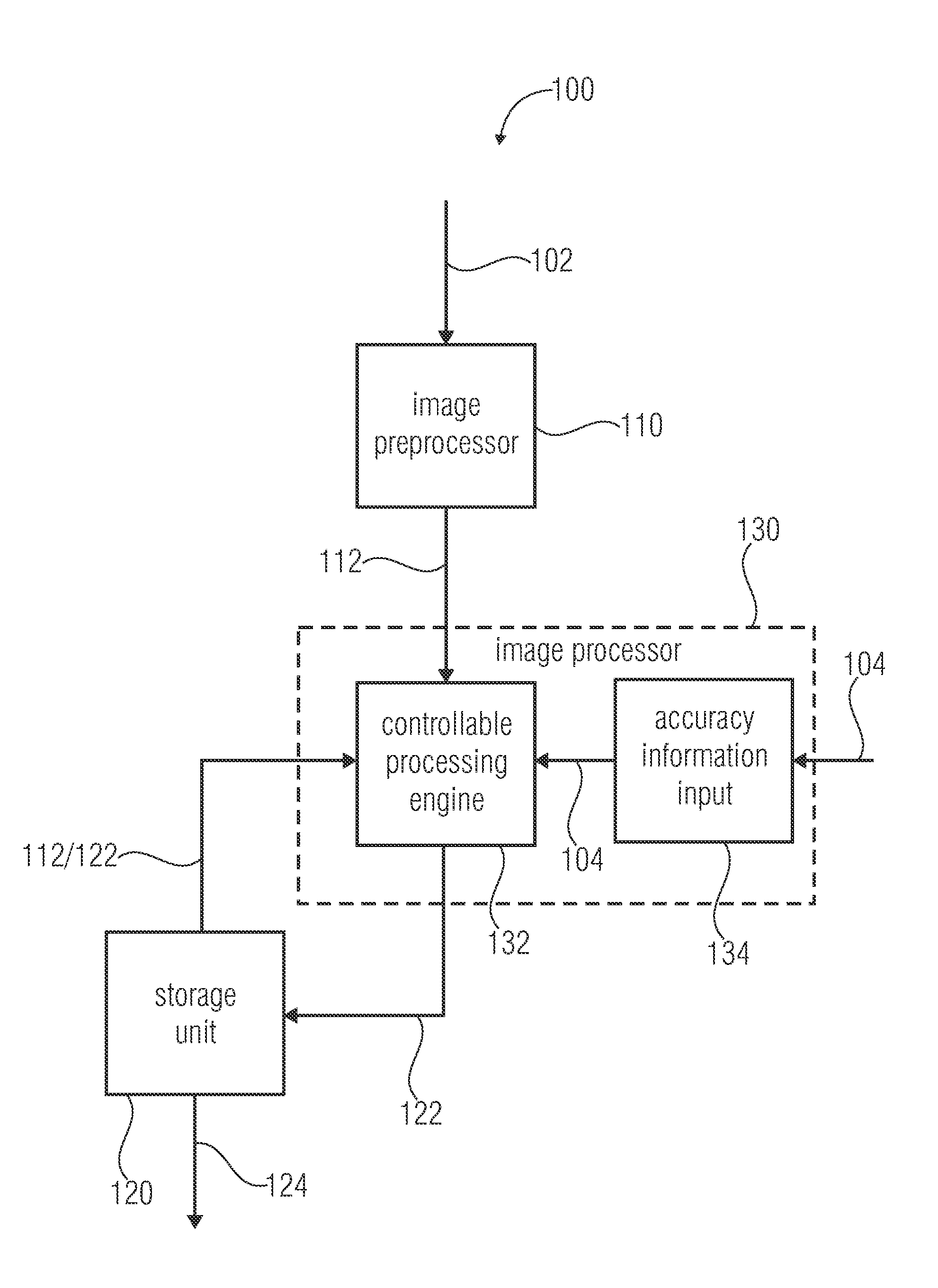
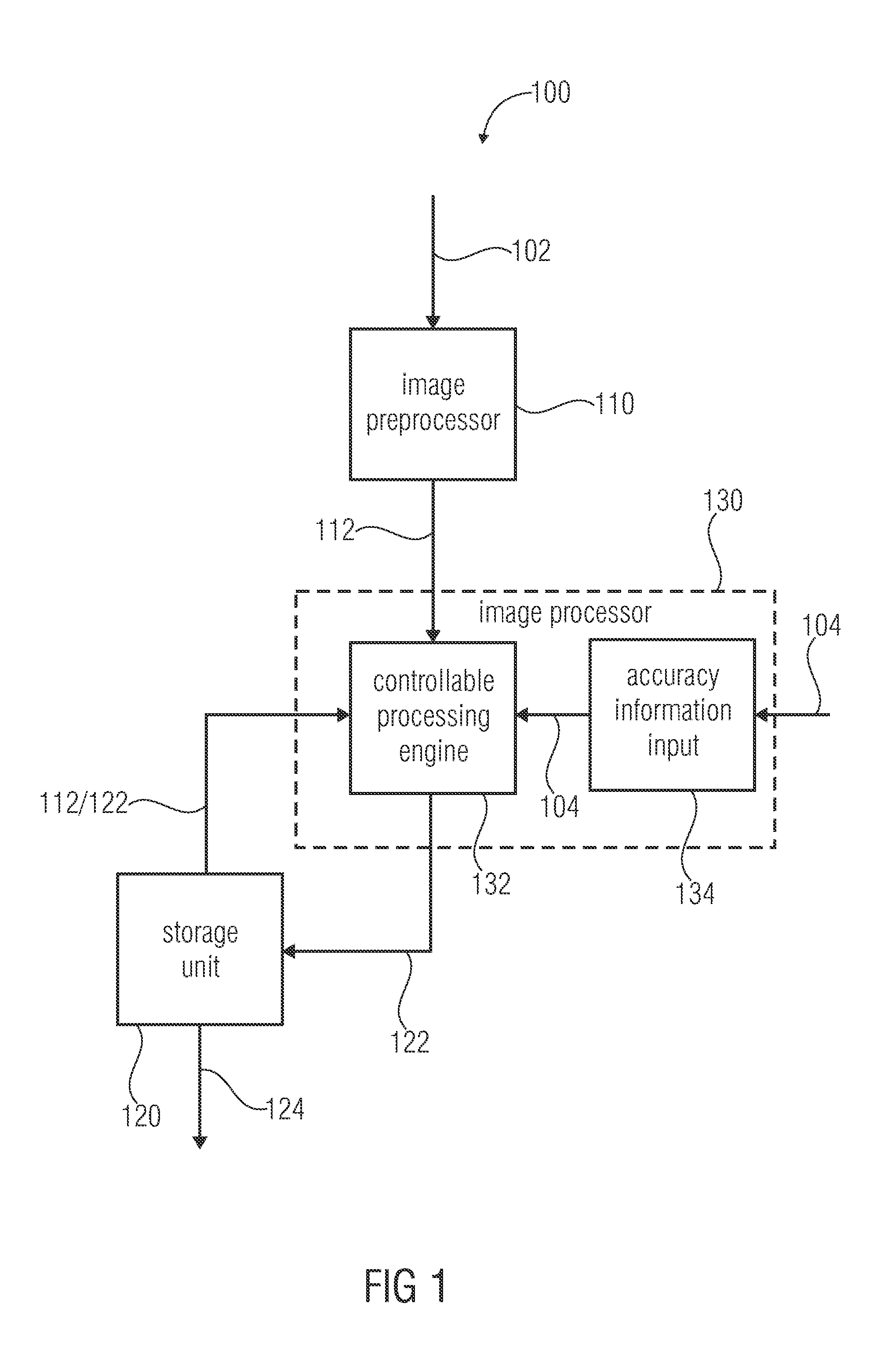
[0038]FIG. 1 shows a block diagram of an apparatus 100 for generating an overview image 124 of a plurality of images according to an embodiment of the invention. Each image of the plurality of images comprises associated meta-data. The apparatus 100 comprises an image preprocessor 110, a storage unit 120 and an image processor 130. The image preprocessor 110 is connected to the image processor 130 and the image processor 130 is connected to the storage unit 120. The image preprocessor 110 preprocesses a new image 102 by assigning the new image 102 to a position in the overview image 124 based on a position information contained by the meta-data of the new image 102. Further, the stora...


PUM


Abstract

An apparatus for generating an overview image of a plurality of images comprises a storage unit and an image processor. The storage unit stores a plurality of processed images of the overview image and is able to provide the overview image containing the plurality of processed images at their assigned positions for displaying. The image processor determines feature points of a new image and compares the determined feature points of the new image with feature points of a stored processed image to identify common feature points and to obtain 3-dimensional positions of the common feature points. Further, the image processor determines common feature points located within a predefined maximum distance of relevance to a reference plane based on the 3-dimensional positions of the common feature points to identify relevant common feature points. Further, the image processor processes the new image by assigning the new image to a position in the overview image based on a comparison of an image information of each relevant common feature point of the new image with an image information of each corresponding relevant common feature point of the stored processed image without considering common feature points located beyond the predefined maximum distance of relevance to the reference plane.

Description

CROSS-REFERENCE TO RELATED APPLICATIONS[0001]This application claims priority from European Patent Application No. 10174019.9, which was filed on Aug. 25, 2010, and is incorporated herein in its entirety by reference.BACKGROUND OF THE INVENTION[0002]Embodiments according to the invention relating to the field of image processing and particularly an apparatus and a method for generating an overview image of the plurality of images.[0003]Much research has been done in the area of mosaicking of aerial imagery and surveillance over the past years. Many approaches have been proposed ranging from using low altitude imagery of stationary cameras and UAVs (unmanned aerial vehicle) to higher altitudes imagery captured from balloons, airplanes, and satellites. High altitude imagery and on-ground mosaicking such as panoramic image construction are dealing with different challenges than low altitude imagery.[0004]There has been a breakthrough regarding the seamless stitching in past years by ex...

Claims


Application Information

Patent Timeline
Patent Type & Authority Applications(United States)
IPC IPC(8): H04N7/18G06K9/00
CPCG06K2009/2045G06T2207/30181G06T2200/32G06T7/0028G06T7/33G06V10/16
Inventor RINNER, BERNHARDQUARITSCH, MARKUSWISCHOUNIG-STRUCL, DANIELYAHYANEJAD, SAEED
Owner LAKESIDE LAB
Why Eureka
Try Eureka