Mobile radar and planar antenna

a technology of mobile radar and planar antenna, which is applied in the direction of antennas, multi-channel direction-finding systems using radio waves, instruments, etc., can solve the problem of high accuracy in the azimuth angle detection of obstacles, one of the challenges, and achieve the effect of wide azimuth detection range and high resolution performan

Inactive Publication Date: 2009-10-29
HITACHI LTD
View PDF24 Cites 93 Cited by
  • Summary
  • Abstract
  • Description
  • Claims
  • Application Information

AI Technical Summary

Benefits of technology

[0021]According to the present invention, even if the number of antenna elements is increased for narrowing the beam angle, a short distance between the receiving antennas can be maintained, and a return of the phase difference of the receive signal can be reduced. Also, since the phase characteristics of the innermost ...

Problems solved by technology

The high performance, cost reduction, and downsizing of the automotive radar together with the above diversif...

Method used


Image

  • Mobile radar and planar antenna
  • Mobile radar and planar antenna
  • Mobile radar and planar antenna

Examples


first embodiment

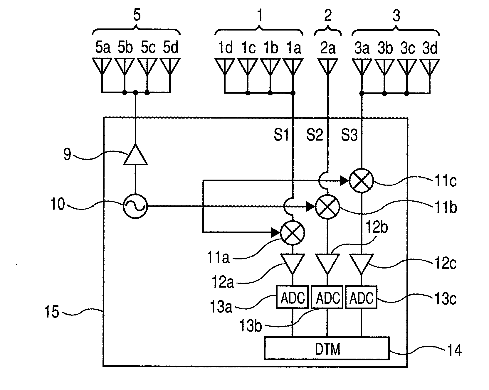
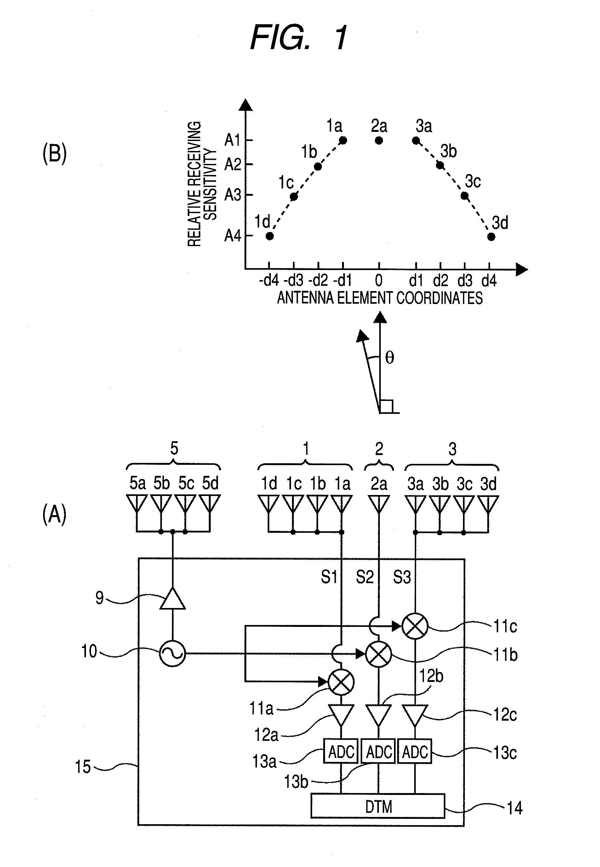
[0052]First, a first embodiment of the present invention will be described with reference to FIGS. 1 to 6. In FIG. 1, (A) is a conceptual diagram showing the configuration of a mobile radar according to the first embodiment. (B) of FIG. 1 is a diagram showing a relationship between antenna element coordinates and a relative receiving sensitivity of the mobile radar shown in (A) of FIG. 1.

[0053]In (A) of FIG. 1, the automotive radar includes a planar antenna having one transmitting array antenna 5 and three receiving array antennas 1, 2, and 3, and a transmitter-receiver unit 15. A radio wave transmitted from the transmitting array antenna is reflected by at least one obstacle and received by the receiving array antennas 1, 2, and 3, as a receive signal. The receiving array antennas 1, 2, and 3 of the planar antenna are aligned in a horizontal direction. Symbol θ represents an azimuth angle.

[0054]A millimeter wave signal generated by an oscillator 10 of the transmitter-receiver unit ...

second embodiment

[0098]In the first embodiment of the present invention, plural receiving array antennas are divided into two (right and left) groups with one receiving array antenna as a center. Alternatively, a boundary line may be defined between two receiving array antennas to divide plural receiving array antennas into two (right and left) groups.

[0099]FIG. 8 is a configuration diagram showing a mobile radar according to a second embodiment of the present invention. (A) of FIG. 8 is a conceptual diagram showing the configuration of the mobile radar according to the second embodiment, and (B) is a diagram showing a relationship the antenna element coordinates and the relative receiving sensitivity of the mobile radar shown in (A) of FIG. 8. A millimeter wave signal generated by the oscillator 10 is added to the transmitting array antenna 5 through the power amplifier 9. The transmit signal radiated from the transmitting array antenna 5 is reflected by the obstacle, and received by the receiving ...

third embodiment

[0106]The present invention can be applied to a case where four or more constant-velocity obstacles is to be separated and detected, that is, a case where five or more receiving array antennas are necessary.

[0107]FIG. 9 is a configuration diagram showing a mobile radar according to a third embodiment of the present invention. (A) of FIG. 9 is a conceptual diagram showing the configuration of the mobile radar according to the third embodiment, and (B) of FIG. 9 is a diagram showing a relationship between the antenna element coordinates and the relative receiving sensitivity of the mobile radar shown in (A). The transmitting array antenna 5, and the receiving array antennas 1, 2, 6, 4, and 3 are composed of the antenna elements 5a to 5d, 1a to 1d, 2a, 6a, 4a, and 3a to 3d, respectively, and aligned in the horizontal direction. Similarly, in this embodiment, the number (four in this embodiment) of antenna elements of the receiving array antennas 1 and 3 at both outer ends thereof which...


PUM


Abstract

In a conventional automotive radar, a return occurs in a phase difference characteristic necessary for a super-resolution method, resulting in an increase of a detection error, or an extremely narrowed azimuth detection range. A transmitting array antenna, and receiving array antennas are composed of antenna elements respectively, and aligned in a horizontal direction. The weighting of receiving sensitivities of the antenna elements of the receiving array antenna 1 is A1, A2, A3, and A4, which are monotonically decreased from an inner side toward an outer side as represented by A1≧A2≧A3≧A4. On the other hand, the receiving array antenna 3 is symmetrical with the receiving array antenna with respect to the receiving array antenna 1.

Description

CLAIM OF PRIORITY[0001]The present application claims priority from Japanese Patent Application JP 2008-117019 filed on Apr. 28, 2008, the content of which is hereby incorporated by reference into this application.FIELD OF THE INVENTION[0002]The present invention relates to a mobile radar and a planar antenna, and more particularly to a mobile radar which is mounted on a mobile object such as a vehicle, and adapted to detect an azimuth orientation of an obstacle, a relative distance to the mobile object, a relative velocity, or the like, and a planar antenna for the radar.BACKGROUND OF THE INVENTION[0003]JP-A-09-101361 discloses an FM-CW radar that enables plural targets to be detected in the mobile radar mounted on an automobile or the like.[0004]Also, JP-A-2007-240313 discloses an azimuth angle detecting device that executes a space average detecting process when a velocity of a subject vehicle is equal to or lower than a threshold value, and detects the azimuth angle of each targ...

Claims


Application Information

Patent Timeline
IPC IPC(8): G01S13/00G01S13/931
CPCG01S3/74G01S2013/9321G01S7/352G01S13/34G01S13/42G01S13/4454G01S13/4463G01S13/931G01S2007/356G01S2013/0263G01S2013/9375H01Q3/2635G01S7/4017G01S7/4021G01S7/4056G01S2007/4091G01S2007/403G01S7/2813G01S2013/93271G01S7/403G01S7/4091G01S7/356
Inventor SHINODA, HIROSHIMORINAGA, MITSUTOSHI
Owner HITACHI LTD
Why Eureka
Try Eureka