
Positive resist composition and patterning process

a composition and resist technology, applied in the field of positive resist composition and patterning process, can solve the problems of uneven fine line size, extreme exacerbated properties, and rough line edges, and achieve the effects of high rectangularity, reduced rough line edges, and high resolution

Active Publication Date: 2009-11-17
SHIN ETSU CHEM IND CO LTD
View PDF18 Cites 14 Cited by
  • Summary
  • Abstract
  • Description
  • Claims
  • Application Information

AI Technical Summary

Benefits of technology

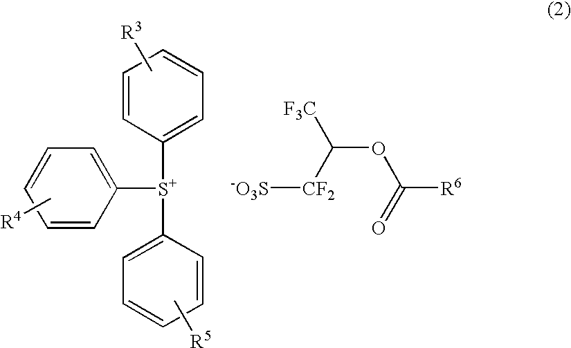
The invention provides a positive resist composition that can be used for precise micropatterning using high-energy radiation such as ArF excimer laser light. The composition has a high resolution and forms a pattern with minimal line edge roughness and high rectangularity. The composition includes a polymer and a sulfonium salt compound as an acid generator. The process for forming a pattern involves applying the composition onto a substrate, heat treating it, and exposing it to high-energy radiation or electron beam through a photomask. The exposing step can be done using immersion lithography. A protective coating can be applied to the resist coating before the exposing step.

Problems solved by technology

However, the ArF excimer laser lithography has not matured so that many problems must be overcome before the technology can be applied to an industrial scale of semiconductor manufacture.
While these prior art resist materials suffer from several problems, the most serious problem is the unevenness of a fine line size generally known as “line edge roughness.” There is a strong desire to solve the problem since such unevenness largely affects the performance of semiconductor devices manufactured.
These approaches, however, extremely exacerbate such properties as exposure dose dependency, pattern density dependency, and mask fidelity, and do not entail a reduction of line edge roughness because fine fluctuations of the mask are enlarged so that the line size itself rather becomes uneven.
Although an attempt was made to introduce monocyclic lactone units having a high developer affinity in order to reduce line edge roughness (see JP-A 2005-54070), it is still short in holding down the diffusion of the generated acid, resulting in insufficient resolution.

Method used


Image

  • Positive resist composition and patterning process
  • Positive resist composition and patterning process
  • Positive resist composition and patterning process

Examples


example

Examples of the invention are given below by way of illustration and not by way of limitation. Mw is weight average molecular weight.

[Preparation of Resist Material]

examples

Positive resist solutions were prepared by dissolving a polymer, acid generator, and basic compound in a solvent in accordance with the formulation shown in Table 1 and passing through a Teflon® filter with a pore size of 0.2 μm. In all runs, the solvent contained 0.005 wt % of surfactant KH-20 (Asahi Glass Co., Ltd.).

TABLE 1ResistResinAcid generatorBaseSolvent 1Solvent 2R-01P-01 (80)PAG-1 (10.1)Base-1 (1.4)PGMEA (1,120)CyHO (480)R-02P-02 (80)PAG-1 (10.1)Base-1 (1.4)PGMEA (1,120)CyHO (480)R-03P-03 (80)PAG-1 (10.1)Base-1 (1.4)PGMEA (1,120)CyHO (480)R-04P-04 (80)PAG-1 (10.1)Base-1 (1.4)PGMEA (1,120)CyHO (480)R-05P-05 (80)PAG-1 (10.1)Base-1 (1.4)PGMEA (1,120)CyHO (480)R-06P-06 (80)PAG-1 (10.1)Base-1 (1.4)PGMEA (1,120)CyHO (480)R-07P-07 (80)PAG-1 (10.1)Base-1 (1.4)PGMEA (1,120)CyHO (480)R-08P-08 (80)PAG-1 (10.1)Base-1 (1.4)PGMEA (1,120)CyHO (480)R-09P-09 (80)PAG-1 (10.1)Base-1 (1.4)PGMEA (1,120)CyHO (480)R-10P-10 (80)PAG-1 (10.1)Base-1 (1.4)PGMEA (1,120)CyHO (480)R-11P-11 (80)PAG-1 (10....


PUM

PropertyMeasurementUnit
refractive indexaaaaaaaaaa
wavelengthaaaaaaaaaa

Abstract

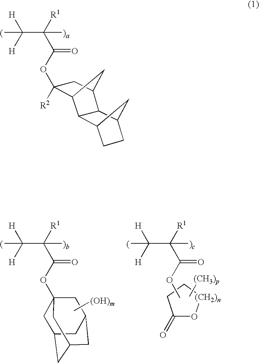
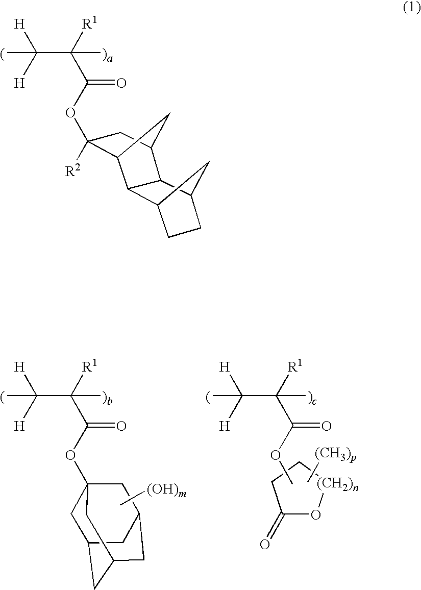
A positive resist composition comprises (A) a resin component which becomes soluble in an alkaline developer under the action of an acid, and (B) an acid generator which is a specific sulfonium salt compound. The resin (A) is a polymer comprising tertiary alkyl protective group units having a hydrophobic tetracyclo[4.4.0.12,5.17,10]dodecane structure, di- or trihydroxyadamantyl units, and monocyclic lactone units.

Description

CROSS-REFERENCE TO RELATED APPLICATIONThis non-provisional application claims priority under 35 U.S.C. §119(a) on Patent Application No. 2007-001374 filed in Japan on Jan. 9, 2007, the entire contents of which are hereby incorporated by reference.TECHNICAL FIELDThis invention relates to a positive resist composition for the micropatterning technology which is improved in resolution, pattern density dependency, and mask fidelity, and forms a pattern with a minimal line edge roughness and good rectangularity, and a patterning process using the same.BACKGROUND ARTIn the recent drive for higher integration and operating speeds in LSI devices, it is desired to miniaturize the pattern rule. Great efforts have been devoted for the development of the micropatterning technology using deep-ultraviolet (deep-UV) or vacuum-ultraviolet (VUV) lithography. The photolithography using KrF excimer laser (wavelength 248 nm) as the light source has already established the main role in the commercial ma...

Claims


Application Information

Patent Timeline
Patent Type & Authority Patents(United States)
IPC IPC(8): G03F7/004G03F7/30
CPCG03F7/0045G03F7/2041G03F7/0397G03F7/0046Y10S430/122Y10S430/111Y10S430/123G03F7/039
Inventor NISHI, TSUNEHIROTACHIBANA, SEIICHIROKOBAYASHI, KATSUHIRO
Owner SHIN ETSU CHEM IND CO LTD
Learn More