Lens module

a technology of lens module and lens module, which is applied in the field of lens module for camera, can solve the problems of difficult to achieve a relatively bright optical system in the plastic lens as compared to the glass lens, limit in realizing a highly-functional camera having high-resolution, and difficult to improve chromatic aberration, etc., and achieves bright optical system and high-resolution performance.

Active Publication Date: 2014-03-18
SAMSUNG ELECTRO MECHANICS CO LTD
View PDF13 Cites 15 Cited by
  • Summary
  • Abstract
  • Description
  • Claims
  • Application Information

AI Technical Summary

Benefits of technology

[0012]An aspect of the present invention provides a lens module capable of realizing a high-resolution performance and a bright optical system.

Problems solved by technology

However, there is a trend for mobile terminals to be smaller and a lighter weight, and thus, there may be a limit in realizing a highly-functional camera having high-resolution.
However, an improvement of chromatic aberration is more difficult in a lens made of plastic than in a lens made of glass, and also, it is difficult to realize a relatively bright optical system in the plastic lens as compared to the glass lens.

Method used


Image

  • Lens module
  • Lens module
  • Lens module

Examples


first embodiment

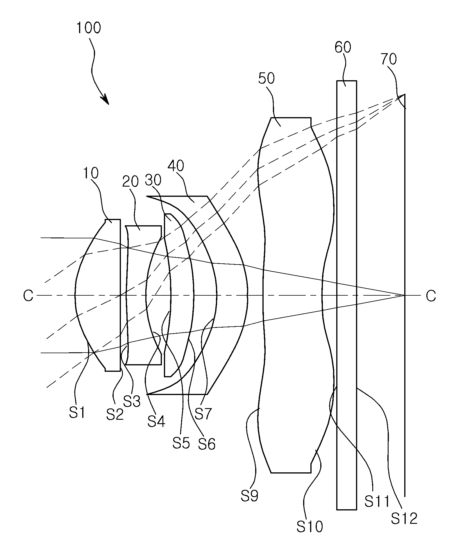
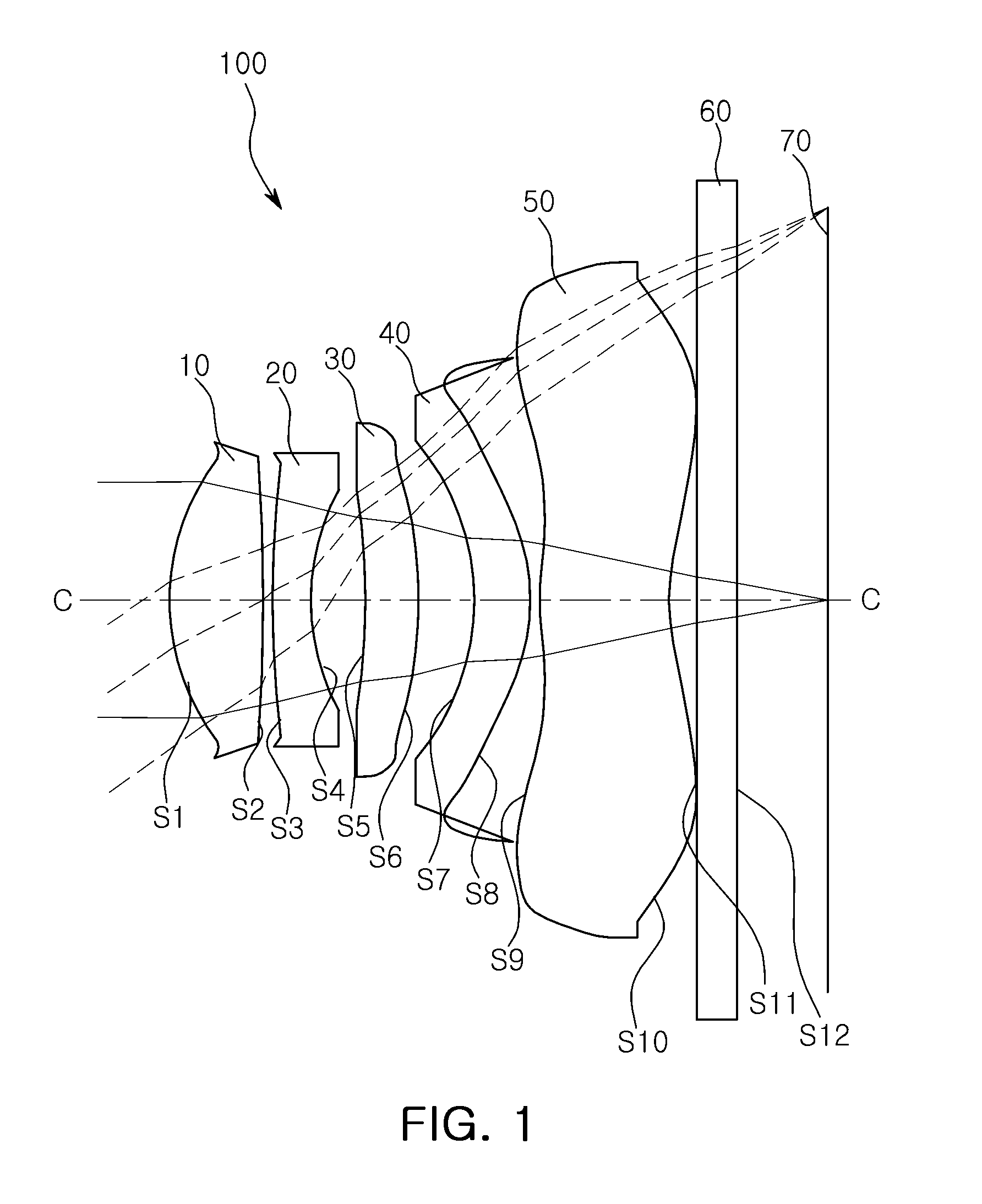
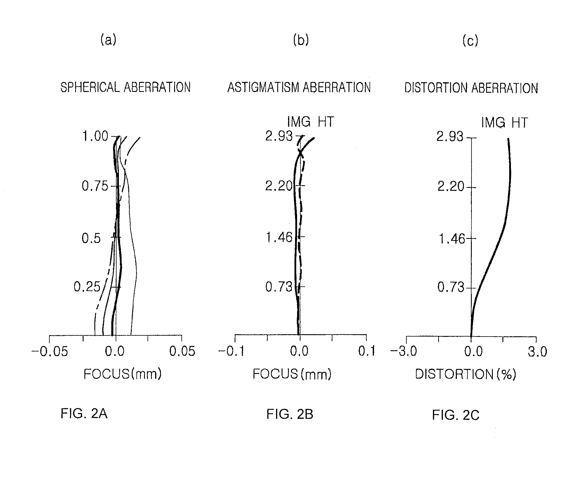
[0114]The lens module 100 according to the first embodiment of the present invention will be described with reference to FIGS. 1, 2A, 2B, and 2C.

[0115]The lens module 100 according to the first embodiment may include the first lens 10 having positive refractive power, the second lens 20 having negative refractive power, the third lens 30 having positive refractive power, the fourth lens 40 having negative refractive power, and the fifth lens 50 having negative refractive power.

[0116]

TABLE 1Radius ofThickness orRefractiveAbbe No.Surface No.CurvatureDistanceIndex(ν)S11.3810.631.54456.1S28.9240.09S34.6560.301.63223.4S41.9880.37S5−6.1070.371.54456.1S6−2.6830.42S7−1.2940.441.63524S8−1.5910.10S92.6740.861.54456.1S101.6840.18S11Infinity0.301.51764.2S12Infinity0.71imgInfinity

[0117]In the lens module 100 of the present embodiment, the focal distance f1 of the first lens 10 is 2.91 mm; the focal distance f2 of the second lens 20 is −5.68 mm; the focal distance f3 of the third lens 30 is 8.44 ...

second embodiment

[0119]The lens module 100 according to the second embodiment of the present invention will be described with reference to FIGS. 3, 4A, 4B, and 4C.

[0120]The lens module 100 according to the second embodiment may include the first lens 10 having positive refractive power, the second lens 20 having negative refractive power, the third lens 30 having positive refractive power, the fourth lens 40 having negative refractive power, and the fifth lens 50 having negative refractive power.

[0121]

TABLE 3Radius ofThickness orRefractiveAbbe No.Surface No.CurvatureDistanceIndex(ν)S11.4060.651.54456.1S211.6510.09S34.6240.281.63223.4S41.9500.37S5−6.4590.331.54456.1S6−2.6250.33S7−1.2200.441.63524S8−1.4190.22S93.3790.851.54456.1S101.7590.21S11Infinity0.301.51764.2S12Infinity0.70imgInfinity

[0122]In the lens module 100 of the present embodiment, the focal distance f1 of the first lens 10 is 2.86 mm; the focal distance f2 of the second lens 20 is −5.50 mm; the focal distance f3 of the third lens 30 is 7....

third embodiment

[0124]The lens module 100 according to the third embodiment of the present invention will be described with reference to FIGS. 5, 6A, 6B, and 6C.

[0125]The lens module 100 according to the third embodiment may include the first lens 10 having positive refractive power, the second lens 20 having negative refractive power, the third lens 30 having positive refractive power, the fourth lens 40 having negative refractive power, and the fifth lens 50 having negative refractive power.

[0126]Here, the first surface S5 of the third lens 30 may be convex toward the object, unlike the other embodiments. In addition, the fourth lens 40 may have an inflection point at a peripheral portion based on the optical axis (C-C) as shown in FIG. 5.

[0127]

TABLE 5Radius ofThickness orRefractiveAbbe No.Surface No.CurvatureDistanceIndex(ν)S11.4360.641.54456.1S26.6300.08S33.3580.271.63223.4S41.7060.45S513.1880.481.54456.1S6−3.7900.22S7−1.0610.331.61425.6S8−1.2070.28S94.9240.961.54456.1S101.8830.17S11Infinity0.3...


PUM


Abstract

There is provided a lens module, including: a first lens having positive refractive power, an object-sided surface thereof being convex; a second lens having negative refractive power, an image-sided surface thereof being concave; a third lens having positive refractive power; a fourth lens having negative refractive power, an image-sided surface thereof being convex; and a fifth lens having negative refractive power, an image-sided surface thereof being concave, wherein the fourth lens satisfies Conditional Expression 1,[Conditional Expression 1]f⁢⁢4f<-3.0where f is an overall focal distance of an optical system and f4 is a focal distance of the fourth lens.

Description

CROSS-REFERENCE TO RELATED APPLICATIONS[0001]This application claims the priority of Korean Patent Application No. 10-2012-0062652 filed on Jun. 12, 2012, in the Korean Intellectual Property Office, the disclosure of which is incorporated herein by reference.BACKGROUND OF THE INVENTION[0002]1. Field of the Invention[0003]The present invention relates to a lens module for a camera, and more particularly, to a lens module capable of realizing a high-resolution performance and a bright optical system.[0004]2. Description of the Related Art[0005]Recent mobile communications terminals have a camera provided therewith, allowing for video communications and photography. In addition, as the functionality of cameras included in mobile terminals has gradually increased, cameras for a mobile terminal have gradually been required to have high resolution and high functionality.[0006]However, there is a trend for mobile terminals to be smaller and a lighter weight, and thus, there may be a limit ...

Claims


Application Information

Patent Timeline
Patent Type & Authority Patents(United States)
IPC IPC(8): G02B13/18G02B9/60
CPCG02B9/60H04N5/2254G02B13/18G02B13/0045G02B13/0015G02B13/00
Inventor JUNG, PHIL HOKIM, YOUNG GI
Owner SAMSUNG ELECTRO MECHANICS CO LTD
Why Eureka
Try Eureka