Radio frequency isolation card

a radio frequency isolation and card technology, applied in the field of radio frequency isolation cards, can solve the problems of poor reception sensitivity, poor radiated output, and unsatisfactory leakage signal at one of these ports, and achieve the effects of improving the performance of an antenna, improving the isolation characteristic of the port-to-port antenna, and improving sensitivity

Inactive Publication Date: 2003-02-04
COMMSCOPE TECH LLC
View PDF5 Cites 45 Cited by
  • Summary
  • Abstract
  • Description
  • Claims
  • Application Information

AI Technical Summary

Benefits of technology

The present invention is useful for improving the performance of an antenna by increasing the port-to-port isolation characteristic of the antenna as measured at the port connectors. In general, the present invention achieves this improvement in sensitivity by using a feedback system comprising one or more feedback elements for generating a feedback signal in response to a transmitted signal output by each radiator of the dual polarized antenna. This feedback signal is received by each radiator, also described as a radiating element, and combined with any leakage signal present at the output port of the antenna. Because the feedback signal and the leakage signal are set to the same frequency and are approximately 180 degrees out of phase, this signal summing operation serves to cancel both signals at the output port, thereby improving the port-to-port isolation characteristic of the antenna.
Each feedback element can comprise a photo-etched metal strip supported by a dielectric card made from printed circuit board material. Such feedback elements can provide a high degree of repeatability and reliability in that the manufacturing of such feedback elements can be precisely controlled. For example, the size, shape, and location of the feedback elements on the dielectric supports can be manufactured by using photo etching and milling processes. Such feedback elements are conducive for high volume production environments while maintaining high quality standards. The manufacturing processes for such feedback elements provide the advantage of small tolerances.
Another important feature of the present invention is the high degree of control over the material properties of the feedback element support structure. Each feedback element support structure is typically an insulative material that has electrical and mechanical properties that are conducive to extreme operating environments of antenna arrays. For example, such feedback element support structures can be selected to provide appropriate dielectric constants (relative permeability), lost tangent (conductivity), and coefficient of thermal expansion in order to optimize the isolation between respective antenna elements in an antenna array.
In one exemplary embodiment, the feedback elements can be combined with dual polarized antenna radiators. In such an exemplary embodiment, the feedback elements may improve the isolation characteristic of signals between two different polarizations.
In an alternate exemplary embodiment, the feedback elements can be combined with multiple band radiating antenna elements. In this way, signals between different operating frequencies can be isolated from one another.

Problems solved by technology

An undesirable leakage signal can appear at one of these ports as a result of a signal present at the opposite port and part of that signal being electrically coupled, undesirably so, to the opposing port.
Poor receive sensitivity, and poor radiated output, often results due to degraded internal antenna loss when part of one of the signals at one input port (port one) leaks or is otherwise coupled as a leakage signal to the other port (port two).
Such leakage or undesired coupling of a signal from one port to the other adversely combines with the signal at the other port to diminish the strength of both signals and hence reduce the effectiveness of the antenna.
When port-to-port isolation is minimal, i.e., leakage is maximum, the antenna system will perform poorly in the receive mode in that the reception of incoming signals will be limited only to the strongest incoming signals and lack the sensitivity to pick up faint signals due to the presence of leakage signals interfering with the weaker desired signals.
In the transmit mode, the antenna performs poorly due to leakage signals detracting from the strength of the radiated signals.
Impedance mismatch can cause leakage signals to occur and degrade the port-to-port isolation if (1) a cross-coupling mechanism is present within the distribution network or in the radiating elements, or if (2) reflecting features are present beyond the radiating elements.
In a dual polarized antenna system, the reflected signal can result in a leakage signal at the opposite port or the same port and it can cause a significant degradation in the overall isolation characteristic and performance of the antenna system.
While impedance matching helps to increase port-to-port isolation, it falls short of achieving the high degree of isolation that is now required in the wireless communications industry.
However, the physical area and dimensional constraints placed on the antenna designs of today for use in cellular base station towers generally render the physical separation technique impractical in all but a few instances.
These techniques can help in increments, but do not solve the magnitude of the signal leakage problem.
While the conductors, according to this technique, can increase the isolation characteristic, the foam bars that support the conductive strips have mechanical properties that are not conducive to the operating environment of the antenna.
Such materials are usually bulky and are difficult to accurately position between antenna elements.
Additionally, these support blocks have coefficients of thermal expansion that are typically not conducive to extreme temperature fluctuations in the outside environment in which the antenna functions, and they readily expand and contract depending on temperature and humidity.
In addition to the problems with thermal expansion, the support blocks are also not conducive for rapid and precise manufacturing.
Furthermore, these types of support blocks do not provide for accurate placement of the conductive strips or feedback elements on the distribution network board.
Another problem with this conventional type feedback element is that the element is typically "floating" above its respective ground plane.
Such an ungrounded feedback system is susceptible to electrostatic charging.
The electrostatic charging of these type conductive elements may attract lightning or currents that are formed from lightning.

Method used


Image

  • Radio frequency isolation card
  • Radio frequency isolation card
  • Radio frequency isolation card

Examples


Embodiment Construction

The isolation card of the present invention can solve the aforementioned problems of leakage signals in, especially, a dual polarized antenna and is useful for enhancing antenna performance for wireless communication applications, such as base station cellular telephone service.

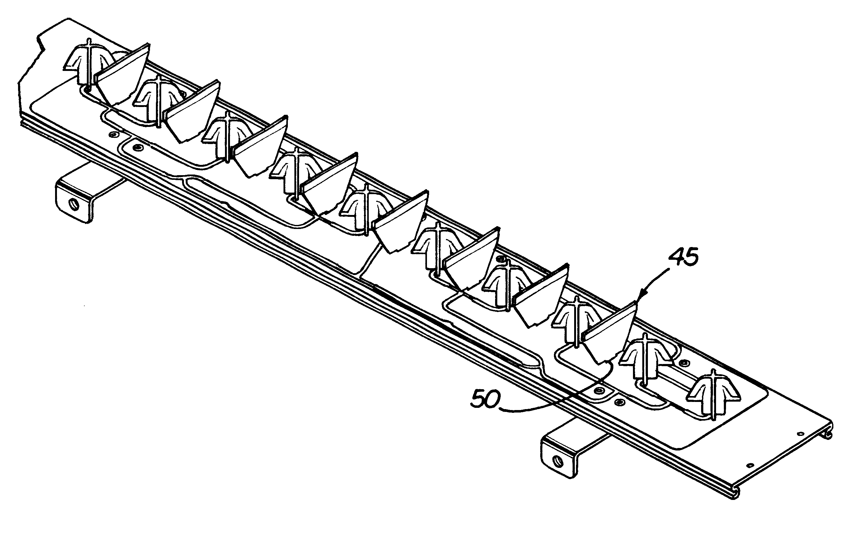
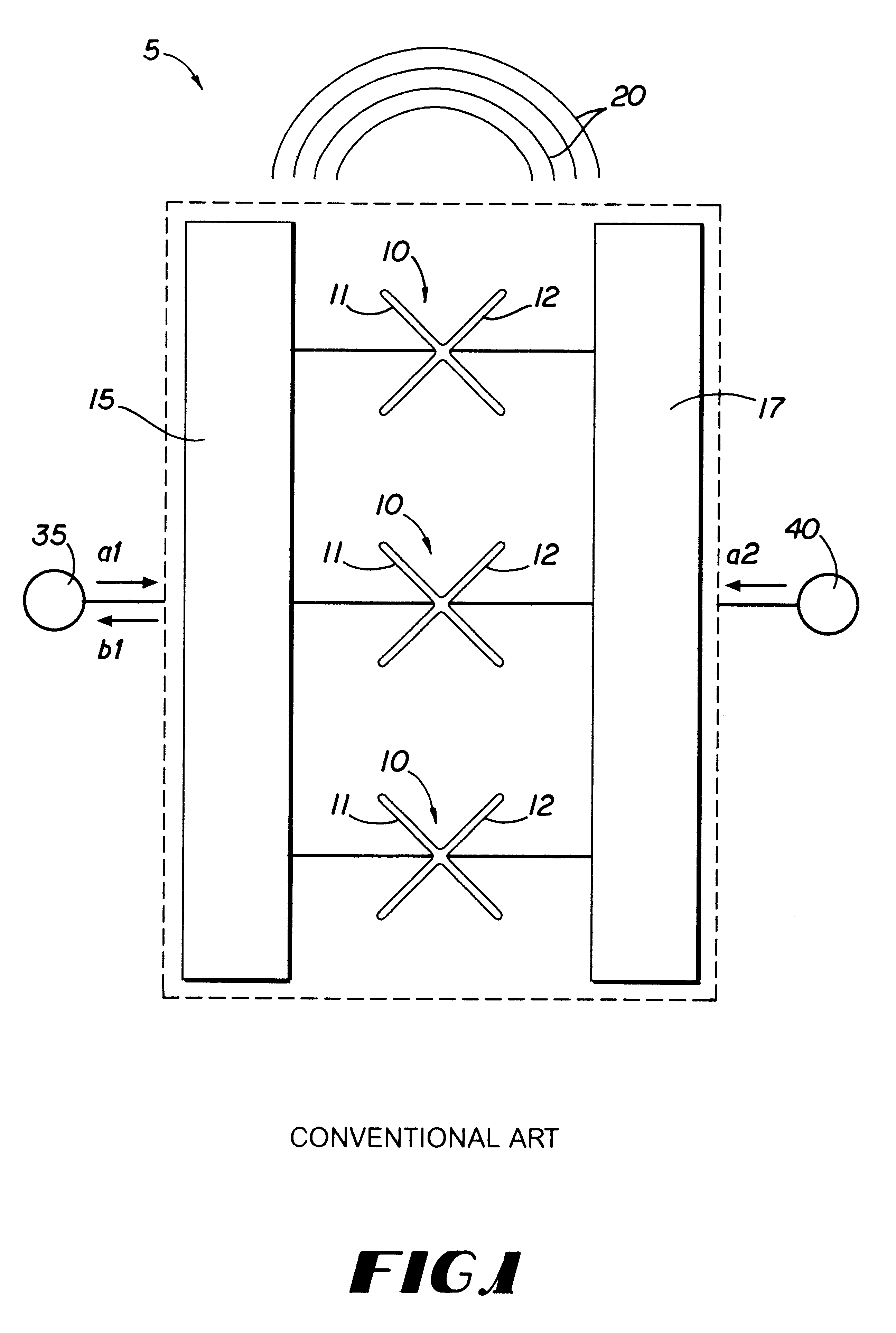
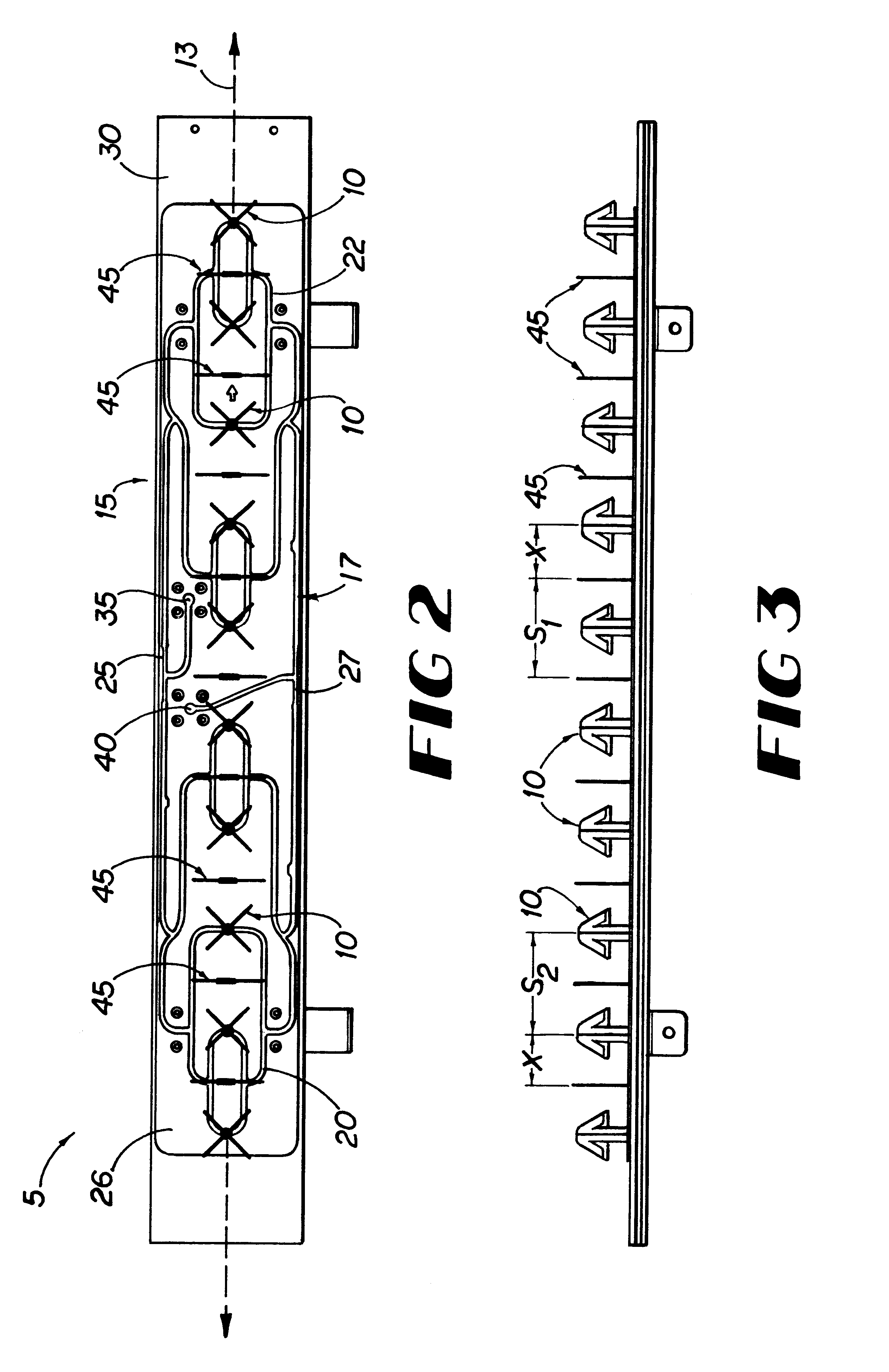
Turning now to the drawings, in which like reference numerals refer to like elements, FIG. 1 is a diagram that illustrates the basic components of a conventional dual polarized antenna 5. Input / output ports 35 and 40 are the connection ports, or antenna terminals, for inputting and / or receiving signals 20. Each port is connected to its respective distribution network 15, 17 that communicates the signal to one of the two differently polarized sub-elements 11 and 12 in a dual polarized radiator of the antenna. In one exemplary embodiment, the dual polarized radiator comprises a crossed dipole 10. Signals of ports 35 and 40 communicate with a four-element array made of dipole radiator elements 10, although it is...


PUM


Abstract

One or more feedback elements generate a feedback signal in response to a transmitted signal outputted by each radiator of the antenna system. This feedback signal is received by each radiator, also described as a radiating element, and combined with any leakage signal present at the port of the antenna. Because the feedback signal and the leakage signal are set to the same frequency and are approximately 180 degrees out of phase, this signal summing operation serves to cancel both signals at the output port, thereby improving the port-to-port isolation characteristic of the antenna. Each feedback element can include a photo-etched planar metal strip supported by a planar dielectric card made from printed circuit board material. Such feedback elements can provide a high degree of repeatability and reliability in that the manufacturing of such feedback elements can be precisely controlled.

Description

This invention relates to antennas for communicating electromagnetic signals and, more particularly, to improving sensitivity of a dual polarized antenna by increasing the isolation characteristic of the antenna.Many types of antennas are in wide use today throughout the communications industry. The antenna has become an especially critical component for an effective wireless communication system due to recent technology advancements in areas such as Personal Communications Services (PCS) and cellular mobile radiotelephone (CMR) service. One antenna type that has advantageous features for use in the cellular telecommunications industry today is the dual polarized antenna which uses a dipole radiator having two radiating sub-elements that are polarity specific to transmit and receive signals at two different polarizations. This type antenna is becoming more prevalent in the wireless communications industry due to the polarization diversity properties that are inherent in the antenna ...

Claims


Application Information

Patent Timeline
Patent Type & Authority Patents(United States)
IPC IPC(8): H01Q21/26H01Q1/24H01Q1/52H01Q1/00H01Q21/24H01Q21/08
CPCH01Q1/246H01Q21/26H01Q21/08H01Q1/523
Inventor IPPOLITO, JOSEPH R.
Owner COMMSCOPE TECH LLC
Why Eureka
Try Eureka