Antenna structure, mobile terminal and antenna mode switching method

A mobile terminal and antenna structure technology, applied in the field of communication, can solve problems such as poor user experience and affecting antenna performance, and achieve the effect of improving antenna performance and user experience

Inactive Publication Date: 2016-11-16
VIVO MOBILE COMM CO LTD
View PDF4 Cites 45 Cited by
  • Summary
  • Abstract
  • Description
  • Claims
  • Application Information

AI Technical Summary

Problems solved by technology

[0004] Embodiments of the present invention provide an antenna structure, a mobile terminal, and a method for switching antenna modes, so as to solve the problem that the lower antenna of the existing mobile terminal is blocked and affects the performance of the antenna, resulting in poor user experience.

Method used


Image

  • Antenna structure, mobile terminal and antenna mode switching method
  • Antenna structure, mobile terminal and antenna mode switching method
  • Antenna structure, mobile terminal and antenna mode switching method

Examples


no. 1 example

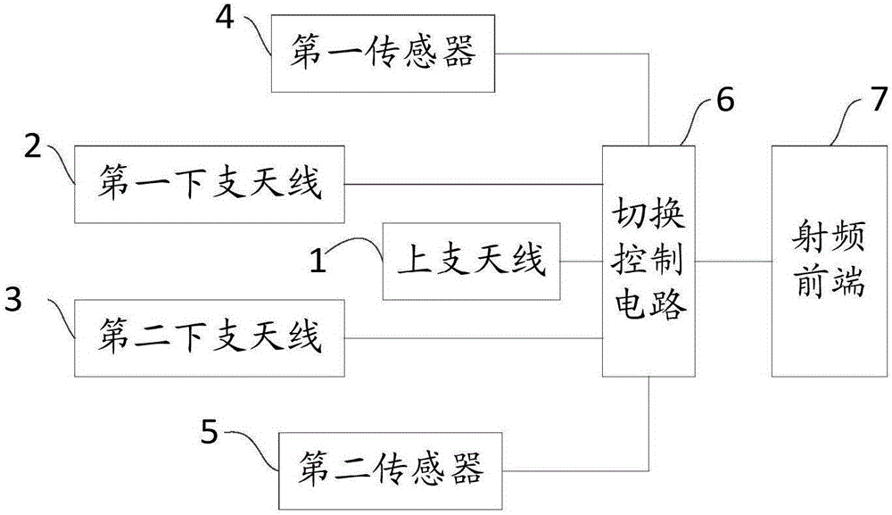
[0022] Such as figure 1 Shown is a schematic diagram of the antenna structure of the mobile terminal in the first embodiment of the present invention. In the first embodiment of the present invention, the antenna structure of the mobile terminal includes an antenna unit, a first sensor 4 , a second sensor 5 and a switching control circuit 6 . Wherein, the antenna unit includes an upper antenna 1 , a first lower antenna 2 and a second lower antenna 3 whose deployment positions do not overlap with each other. Specifically, the first lower antenna 2 and the second lower antenna 3 may be respectively located on two sides below the upper antenna 1 . The first sensor 4 is used to detect whether the first lower antenna 2 is blocked and output a first detection result; the second sensor 5 is used to detect whether the second lower antenna 3 is blocked and output a second detection result. The switching control circuit 6 is connected between the radio frequency front end 7 of the mob...

no. 2 example

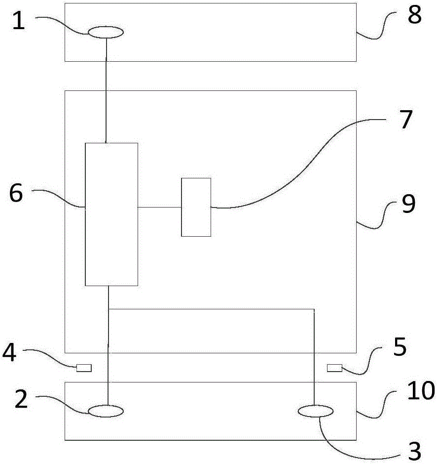
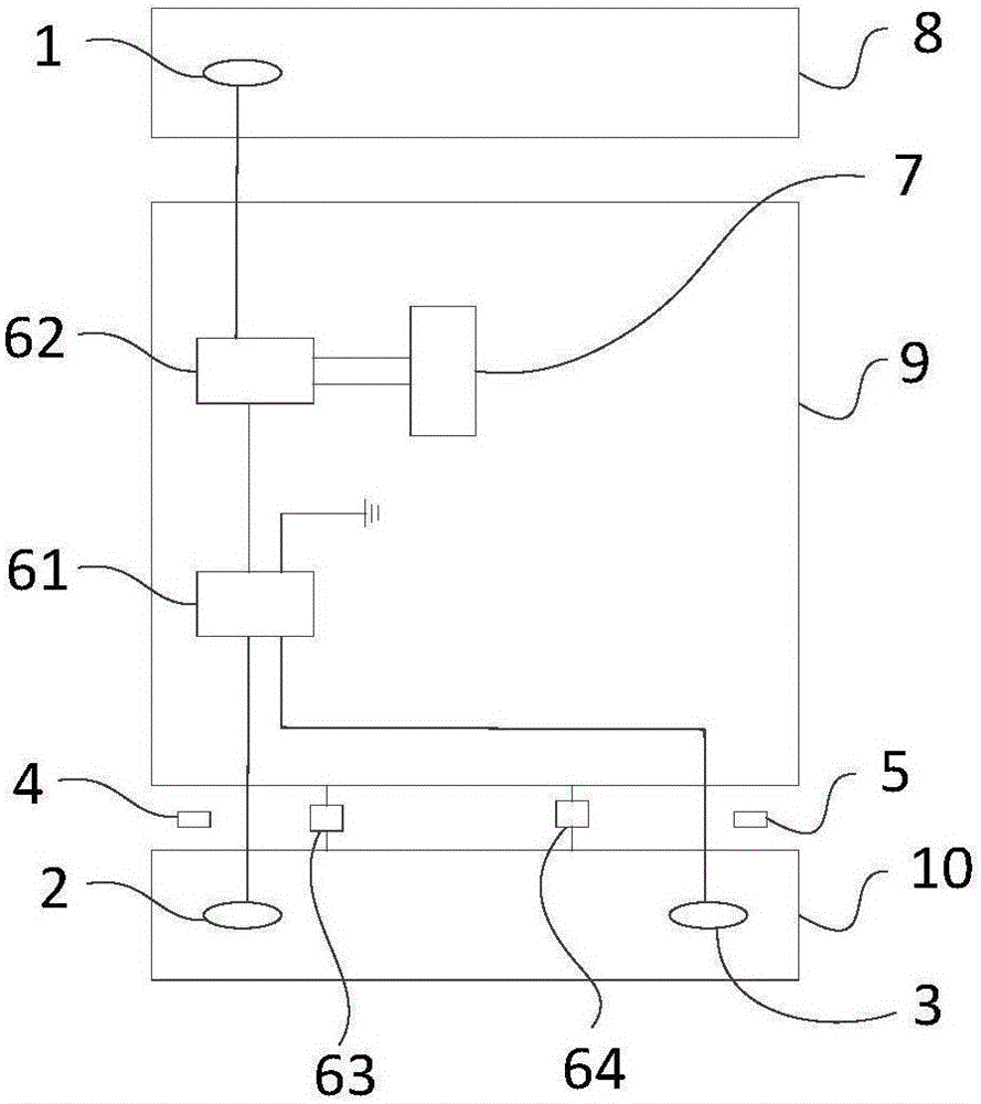
[0032] Such as figure 2 As shown, it is a schematic diagram of the positions of the components on the mobile terminal in the second embodiment of the present invention. In the second embodiment of the present invention, the mobile terminal includes a three-section metal back cover, and the three-section metal back cover includes an upper section 8 of the back cover, a middle section 9 of the back cover and a lower section 10 of the back cover. The mobile terminal also includes a radio frequency front end 7 and the antenna structure of the mobile terminal provided in the first embodiment. Wherein, the antenna structure includes an antenna unit, a first sensor 4 , a second sensor 5 and a switching control circuit 6 . The upper antenna 1 included in the antenna unit is arranged on the upper part 8 of the back cover, and the first lower antenna 2 and the second lower antenna 3 are respectively arranged on the left and right sides of the lower part 10 of the back cover.

[0033]...

no. 3 example

[0047] Such as Figure 4 As shown, it is a flow chart of the steps of the method for switching the antenna mode of the mobile terminal in the third embodiment of the present invention. The switching method is applied to the mobile terminal in the second embodiment, and includes the following steps:


PUM


Abstract

The invention provides an antenna structure, a mobile terminal and an antenna mode switching method, wherein the antenna structure of the mobile terminal comprises an antenna unit, a first sensor, a second sensor and a switching control circuit; the antenna unit comprises an upper branch antenna, a first lower branch antenna and a second lower branch antenna of which the deployment positions are not overlapped mutually; the first sensor is used for detecting whether the first lower branch antenna is blocked and for outputting a first detection result; the second sensor is used for detecting whether the second lower branch antenna is blocked and for outputting a second detection result; and the switching control circuit is connected between a radio frequency front end of the mobile terminal and the antenna unit and used for controlling the connection and disconnection among various antennae in the radio frequency front end and the antenna unit. With adoption of the antenna structure, the problem that the signal reception capability of the mobile terminal is low when the lower branch antenna is blocked can be solved, the antenna property of the mobile terminal is improved and therefore the user experience is improved.

Description

technical field [0001] The present invention relates to the communication field, in particular to an antenna structure, a mobile terminal and a method for switching antenna modes. Background technique [0002] The three-stage metallization of mobile terminals is a typical structure of the appearance of mobile terminals in recent years. In addition, the appearance of mobile terminals similar to the three-stage metallization basically adopts switching between the upper antenna and the lower antenna. In addition, when designing mobile terminal antennas, on the one hand, the SAR (Specific Absorption Rate, electromagnetic wave energy absorption ratio) safety specification requires that the mobile terminal needs to limit the radiation power of the whole machine within a certain range during design; performance, the radiation performance needs to be further improved, combining these two aspects, the designer has to sacrifice the radiation performance of the whole machine, reduce t...

Claims


Application Information

Patent Timeline
Patent Type & Authority Applications(China)
IPC IPC(8): H01Q23/00H01Q1/50H04M1/02
CPCH01Q3/24H01Q23/00H01Q1/50H04M1/0202
Inventor 张声陆
Owner VIVO MOBILE COMM CO LTD
Why Eureka
Try Eureka