Eureka AIR delivers breakthrough ideas for toughest innovation challenges, trusted by R&D personnel around the world.

Foldable Portable Radio Device

a portable radio and antenna technology, applied in the direction of resonant antennas, differential interacting antenna combinations, independent non-interacting antenna combinations, etc., can solve the problems of increasing the loss of measurement frequency, deteriorating antenna performance, and degrading antenna performance of mobile radio apparatuses, and achieve excellent antenna performan

Inactive Publication Date: 2008-06-19
PANASONIC CORP
View PDF1 Cites 47 Cited by
  • Summary
  • Abstract
  • Description
  • Claims
  • Application Information

AI Technical Summary

Benefits of technology

[0029]As described above, according to the folder type mobile radio apparatus according to the present invention, it is possible to obtain excellent antenna performance in either of a calling state that the first casing and the second casing are unfolded or a folded state that the first casing and second casing are folded.

Problems solved by technology

An antenna installed in a mobile radio apparatus may produce degraded performance due to electrical interaction between a user's hand and the antenna in a state when a user holds it by the user's hand for use.
Particularly, in an antenna installed outside the mobile radio apparatus, such as a helical antenna, the antenna performance is further deteriorated due to the significant electrical interaction when the user's hand is disposed near the antenna or a feed part in a state when the user holds it by the user's hand for use.
This is because, if the user's hand is disposed near the antenna or the feed part, the resonant frequency as well as the antenna impedance may vary, so that a mismatching loss increases in a measurement frequency.
How to reduce such electrical interaction is a design issue of an antenna in a mobile radio apparatus industry.

Method used


Image

  • Foldable Portable Radio Device
  • Foldable Portable Radio Device
  • Foldable Portable Radio Device

Examples


first embodiment

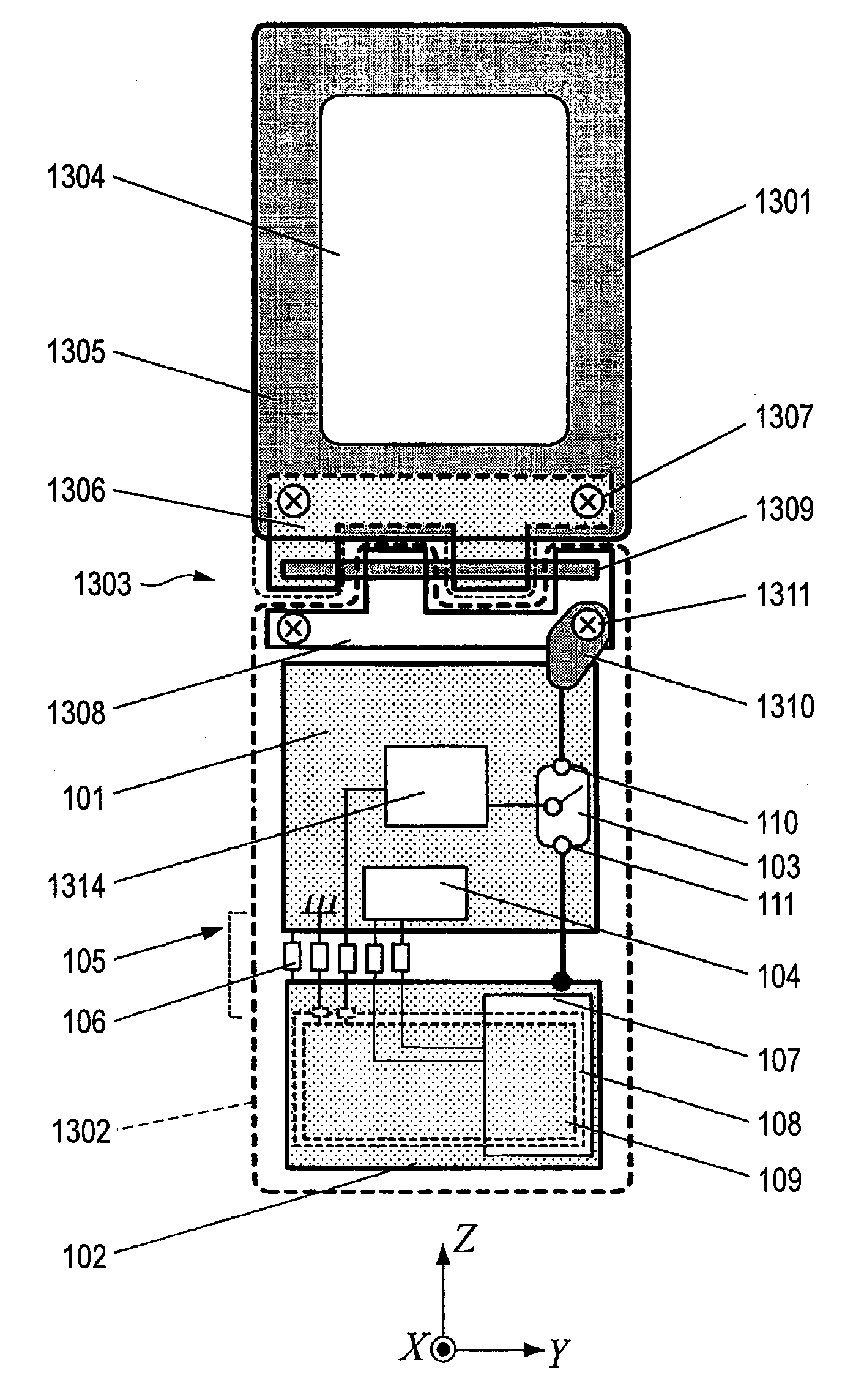
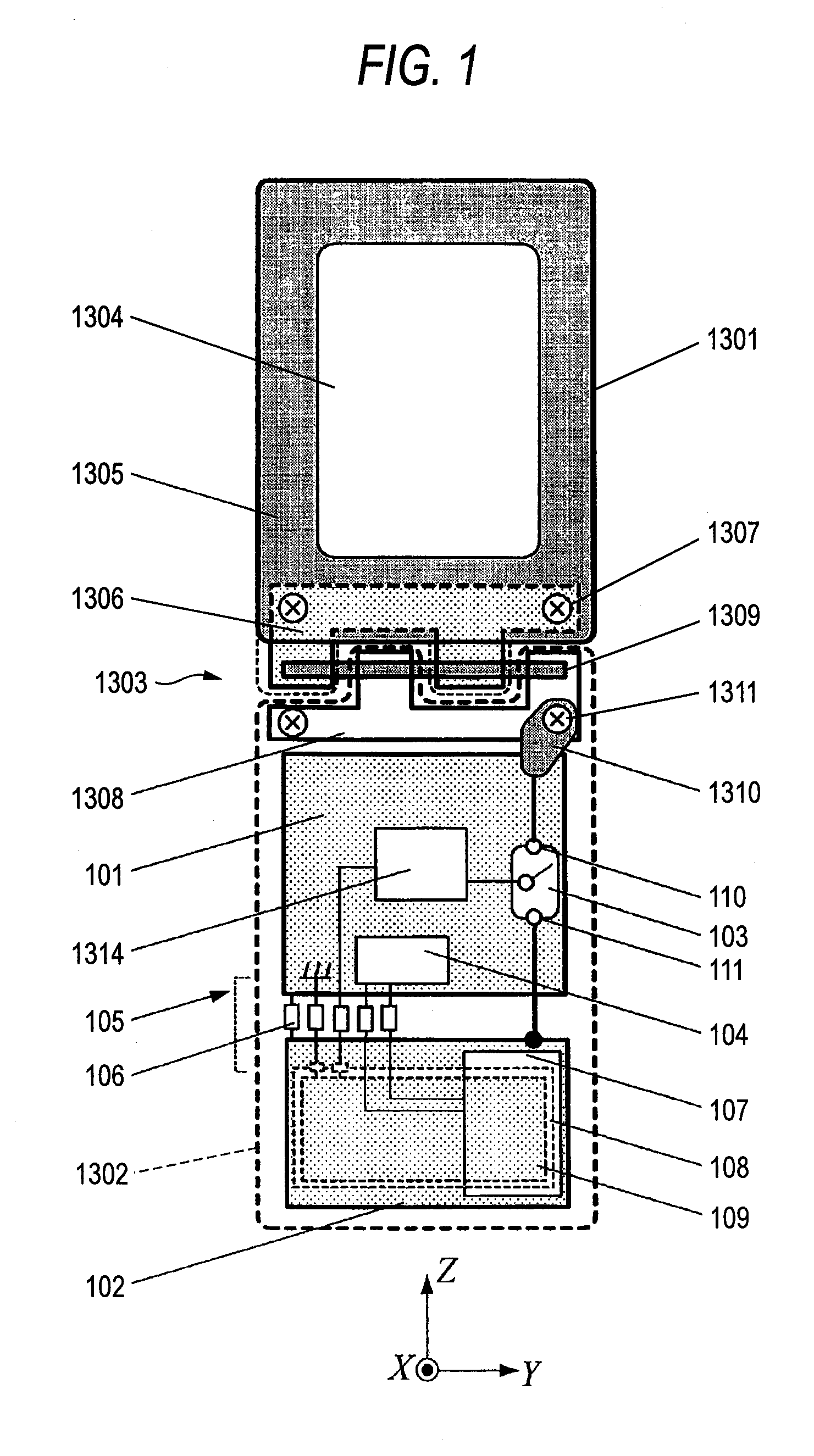
[0083]The folder type mobile radio apparatus according to the first embodiment of the present invention will be described in detail with reference to FIGS. 1 to 7.

[0084]FIG. 1 is a front view illustrating a basic construction of a folder type mobile radio apparatus according to the first embodiment of the present invention.

[0085]As shown in FIG. 1, the folder type mobile radio apparatus according to the first embodiment of the present invention comprises a first circuit board 101, a second circuit board 102, an antenna switching unit 103, a data processing portion 104, a connecting portion 105 for connecting the first circuit board and the second circuit board with each other, and an external memory drive 107 in a lower case 1302.

[0086]The first circuit board 101 is a printed board having a thickness of, for example, 1 mm on which circuit elements for implementing various functions of the folder type mobile radio apparatus are mounted. A ground pattern serving as a ground voltage is...

second embodiment

[0119]A folder type mobile radio apparatus according to the second embodiment of the present invention will now be described in detail with reference to FIG. 8. FIG. 8 is a front view illustrating a basic construction of a folder type mobile radio apparatus according to the second embodiment of the present invention.

[0120]The folder type mobile radio apparatus according to the second embodiment of the present invention relates to an antenna construction in which a circuit board for implementing various functions of the folder type mobile radio apparatus is realized in substantially the same size as that of the first circuit board 101 of the first embodiment.

[0121]As shown in FIG. 8, in the folder type mobile radio apparatus according to the second embodiment of the present invention, the lower case 1302 includes a third circuit board 801, a fourth circuit board 802, an antenna element 803, and a connection terminal portion 804.

[0122]The third circuit board 801 is a printed board hav...

third embodiment

[0128]A folder type mobile radio apparatus according to the third embodiment of the present invention will now be described in detail with reference to FIG. 9. FIG. 9 is a front view illustrating a basic construction of a folder type mobile radio apparatus according to the third embodiment of the present invention.

[0129]As shown in FIG. 9, according to the third embodiment of the present invention, in the lower case 1302 of the folder type mobile radio apparatus of the first embodiment, the electrode metal portion 109 in a battery is used as an antenna element.

[0130]The feed terminal 901 is electrically connected to the electrode metal portion 109 of the battery, and disposed in a symmetrical position with the ground terminal 903 and the power line terminal 904 of the battery across the width of the folder type mobile radio apparatus.

[0131]The feed terminal 901 is connected to the radio circuit 1314 through the connection pin 902. The feed terminal 901 is a metal connector connected...


PUM


Abstract

Regardless of a user's hand holding condition, it is possible to obtain excellent antenna performance in both of folded and unfolded calling conditions. A folder type mobile radio apparatus includes an upper case 1301 having a first antenna element made of a metal plate 1305 , a lower case 1302 having a second antenna element made of a circuit board 102 , a hinge portion 1303 pivotably connecting the upper and lower cases 1301 and 1302 , a first circuit board 101 having a ground pattern provided in an end side near the hinge portion 1303 in the lower case, an antenna switching unit 103 for selecting one of a first feed means for feeding the first antenna element for the radio circuit 1314 on the first circuit board 101 or a second feed means for feeding the second antenna element.

Description

TECHNICAL FIELD[0001]The present invention relates to an antenna of a mobile radio apparatus, and more particularly, to a folder type mobile radio apparatus having superior performance in either of a folded state or a state when a user holds it by a user's hand for use.BACKGROUND ART[0002]An antenna installed in a mobile radio apparatus may produce degraded performance due to electrical interaction between a user's hand and the antenna in a state when a user holds it by the user's hand for use. Particularly, in an antenna installed outside the mobile radio apparatus, such as a helical antenna, the antenna performance is further deteriorated due to the significant electrical interaction when the user's hand is disposed near the antenna or a feed part in a state when the user holds it by the user's hand for use.[0003]This is because, if the user's hand is disposed near the antenna or the feed part, the resonant frequency as well as the antenna impedance may vary, so that a mismatching...

Claims


Application Information

Patent Timeline
Patent Type & Authority Applications(United States)
IPC IPC(8): H01Q1/24H01Q3/24
CPCH01Q1/243H01Q3/24H04M1/0214H01Q21/29H04B1/3833H01Q21/28
Inventor MASHIMA, NOBUHARUSAITO, YUTAKANAKANISHI, HIDEOYAMADA, KENICHI
Owner PANASONIC CORP
Why Eureka
Eureka Blog
Learn More