Method for manufacturing the rotor of induction motor and the rotor using it

Inactive Publication Date: 2012-01-26
GEM CO LTD
View PDF7 Cites 10 Cited by
  • Summary
  • Abstract
  • Description
  • Claims
  • Application Information

AI Technical Summary

Benefits of technology

[0017]According to the construction of the present invention, the conductive bars can be completely bonded to the stacked body in a very simple manner, thereby pre

Problems solved by technology

This is because the rotor is subjected to deformation or defectiveness in joint parts due to a centrifugal force occurring upon ultra high speed revolution of the rotor, thereby causing a weakened balancing feature and reduced lifetime.
Particul

Method used


Image

  • Method for manufacturing the rotor of induction motor and the rotor using it
  • Method for manufacturing the rotor of induction motor and the rotor using it
  • Method for manufacturing the rotor of induction motor and the rotor using it

Examples


Example

[0022]Reference will now be made in greater detail to a preferred embodiment of the invention, an example of which is illustrated in the accompanying drawings. The description and drawings are provided for only illustrative purposes, so the scope of the present invention is not limited thereto. Further, known constructions and functions that may make the present invention ambiguous will be omitted from the description.

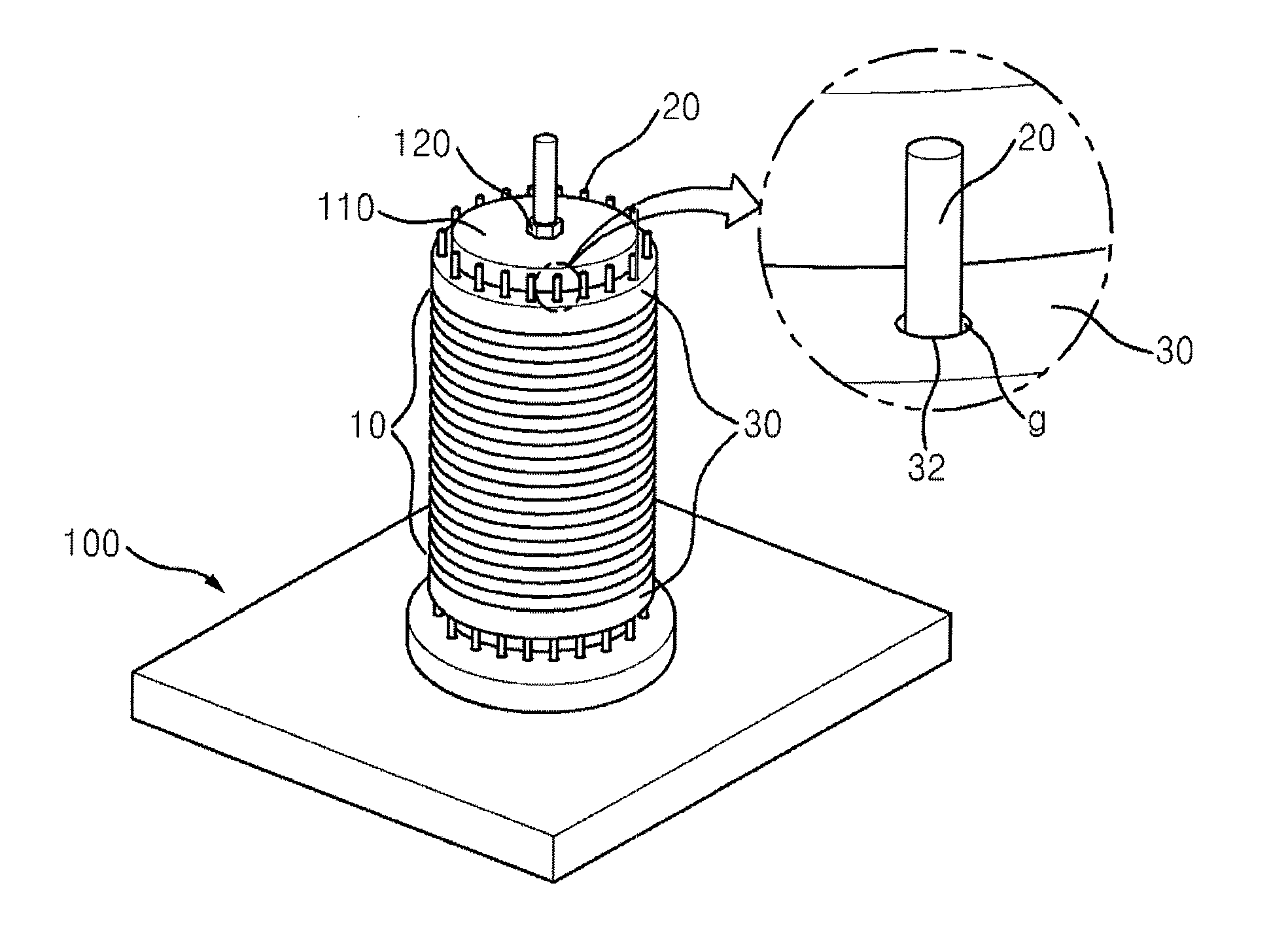
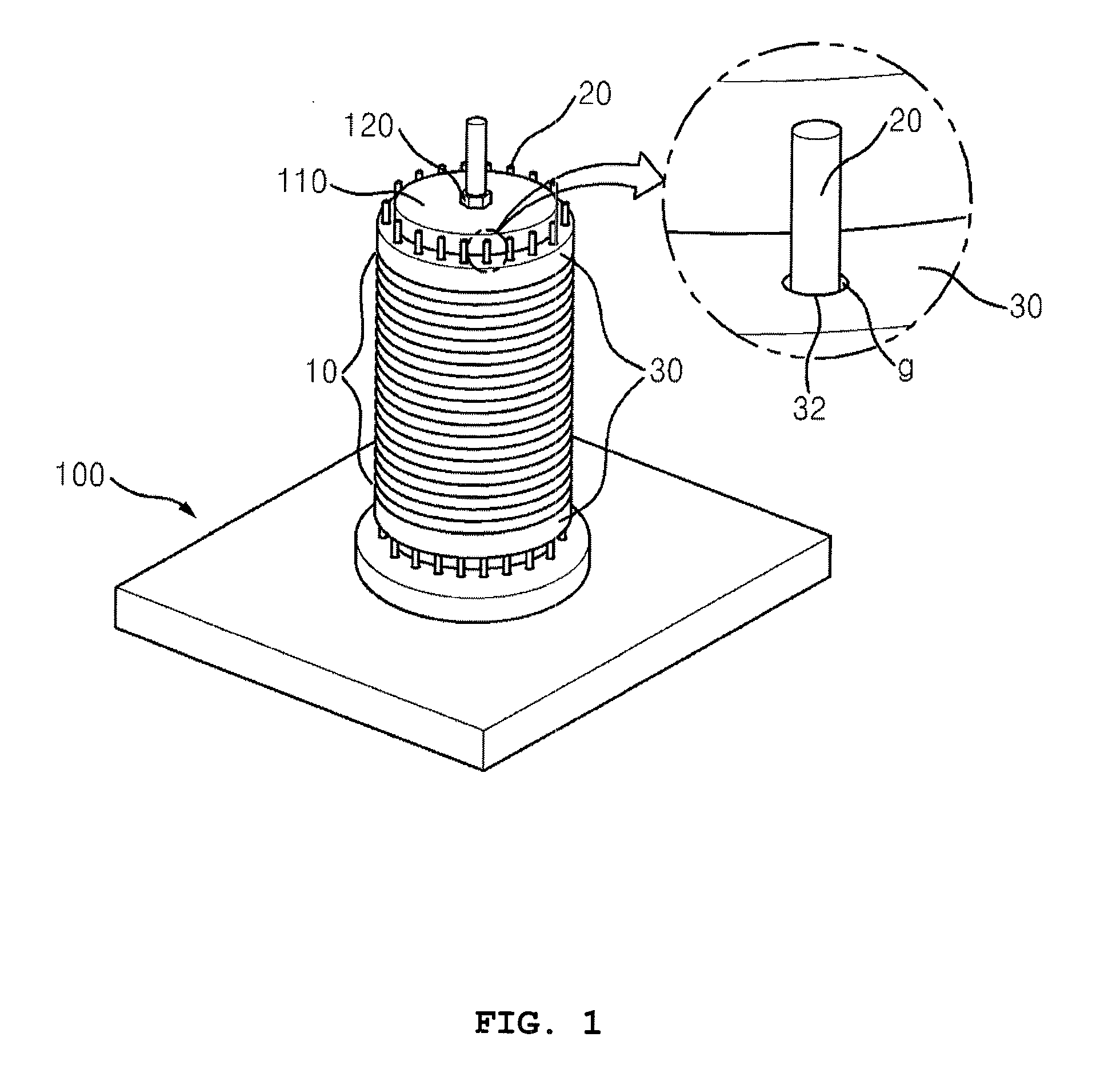
[0023]In an aspect, the present invention provides a rotor of an ultra high speed induction motor, a general structure of which is simply illustrated in FIG. 1.

[0024]The rotor includes in general a stacked body 10, a conductive bar 20, and an end ring 30.

[0025]The stacked body 10 consists of a plurality of loop type electric steel sheets that are stacked to form a cylinder, with a plurality of slots 12 circumferentially formed at regular intervals in the sheets such that the slots 12 are aligned in a longitudinal direction of the stacked body 10.

[0026]The conductive ba...


PUM

PropertyMeasurementUnit
Electrical conductoraaaaaaaaaa

Abstract

A rotor of an ultra high speed induction motor includes a stacked body having a plurality of loop type steel sheets stacked to form a cylinder, with a plurality of slots circumferentially formed in a lengthwise direction of the stacked body. Loop type upper, lower end rings are disposed on the upper and lower portions of the stacked body and having a plurality of upper and lower through-holes, respectively, to correspond to the slots. Conductive bars are coated with fusible bonding flux and are inserted into the upper through-holes, the slots, and the lower through-holes such that the conductive bars are integrally bonded into the upper through-holes, the slots, and the lower through-holes, following the fusion and solidification of the fusible bonding flux.

Description

BACKGROUND OF THE INVENTION[0001]1. Field of the Invention[0002]The present invention relates, in general, to a rotor of an ultra high speed induction motor, in which a conductive bar is coupled to a slot of the rotor, and a method of manufacturing the same.[0003]2. Description of the Related Art[0004]Generally, induction motors are apparatuses that receive electric energy and convert it into a rotational motion, and include a stator, around which windings are distributed, and a cylindrical rotor which is inserted into the stator to cause an induced current by a magnetic field that is induced by alternating current flowing through the stator windings.[0005]FIG. 1 is a perspective view showing a rotor of a conventional induction motor.[0006]The rotor of the conventional induction motor includes a cylindrical stacked body 10 which consists of a plurality of loop type electric steel sheets that are stacked to form a cylinder, with slots (not shown) formed at regular intervals around ci...

Claims


Application Information

Patent Timeline
IPC IPC(8): H02K17/16H02K15/02
CPCH02K17/165H02K15/0081Y10T29/49012H02K15/0012
Inventor HONG, SEUNGSUYANG, SEONGU
Owner GEM CO LTD
Why Eureka
Try Eureka