Detection circuit with correlated double sampling with improved Anti-blooming circuit

a detection circuit and anti-blooming technology, applied in the field of detection circuits with correlated double sampling, can solve problems such as circuits unusable and unsatisfactory circuits, and achieve the effects of reliable and repeatable production, easy implementation and convenient us

Active Publication Date: 2012-05-31
LYNRED
View PDF6 Cites 14 Cited by
  • Summary
  • Abstract
  • Description
  • Claims
  • Application Information

AI Technical Summary

Benefits of technology

[0022]It is a further object of the invention to provide a read method that is easy to implement

Problems solved by technology

The circuit proposed in the document US 2003/0034433 provides an answer to the general problem of the blooming phenomena in theoretical manner, but this circuit is n

Method used


Image

  • Detection circuit with correlated double sampling with improved Anti-blooming circuit
  • Detection circuit with correlated double sampling with improved Anti-blooming circuit
  • Detection circuit with correlated double sampling with improved Anti-blooming circuit

Examples


Embodiment Construction

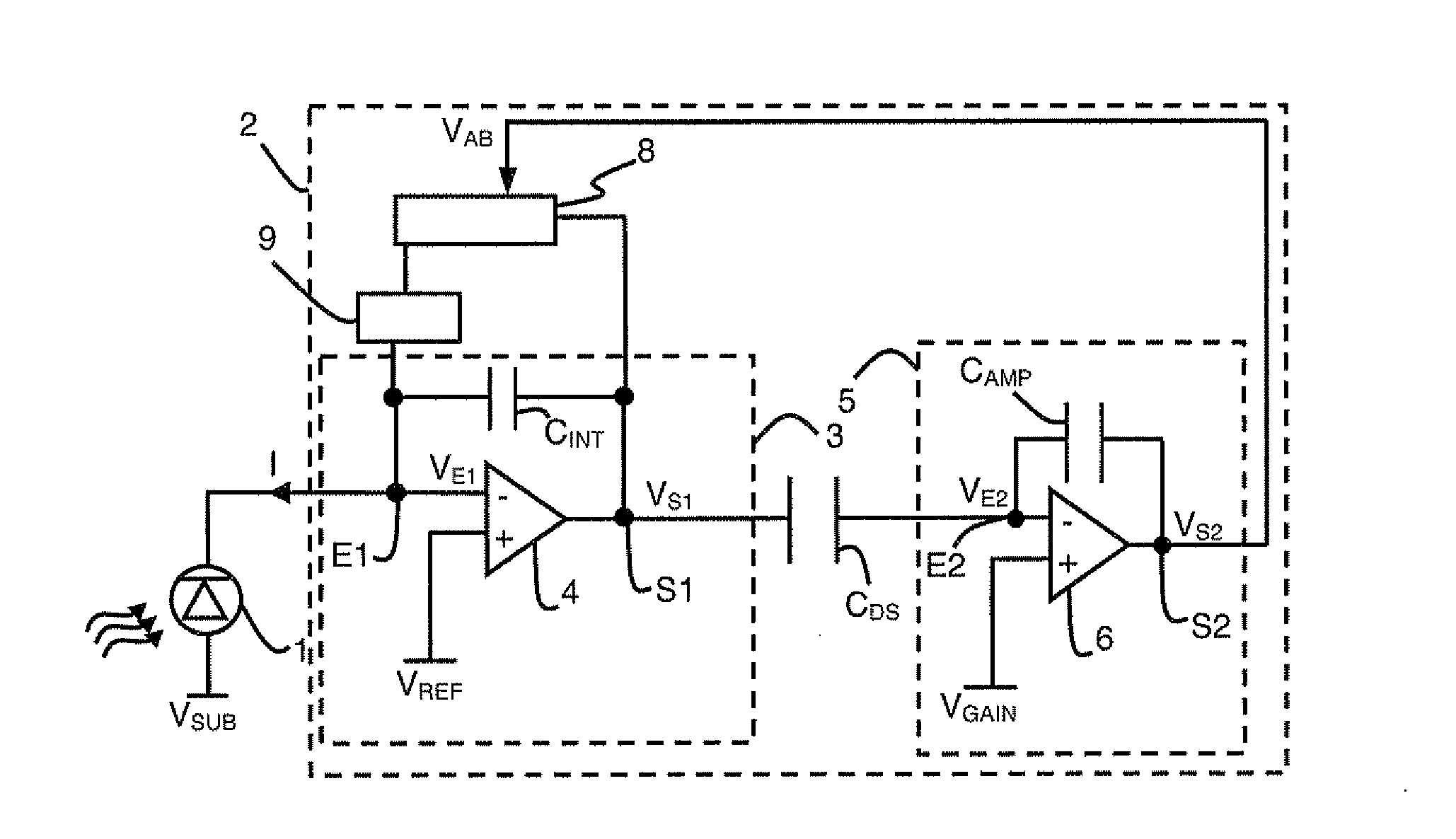
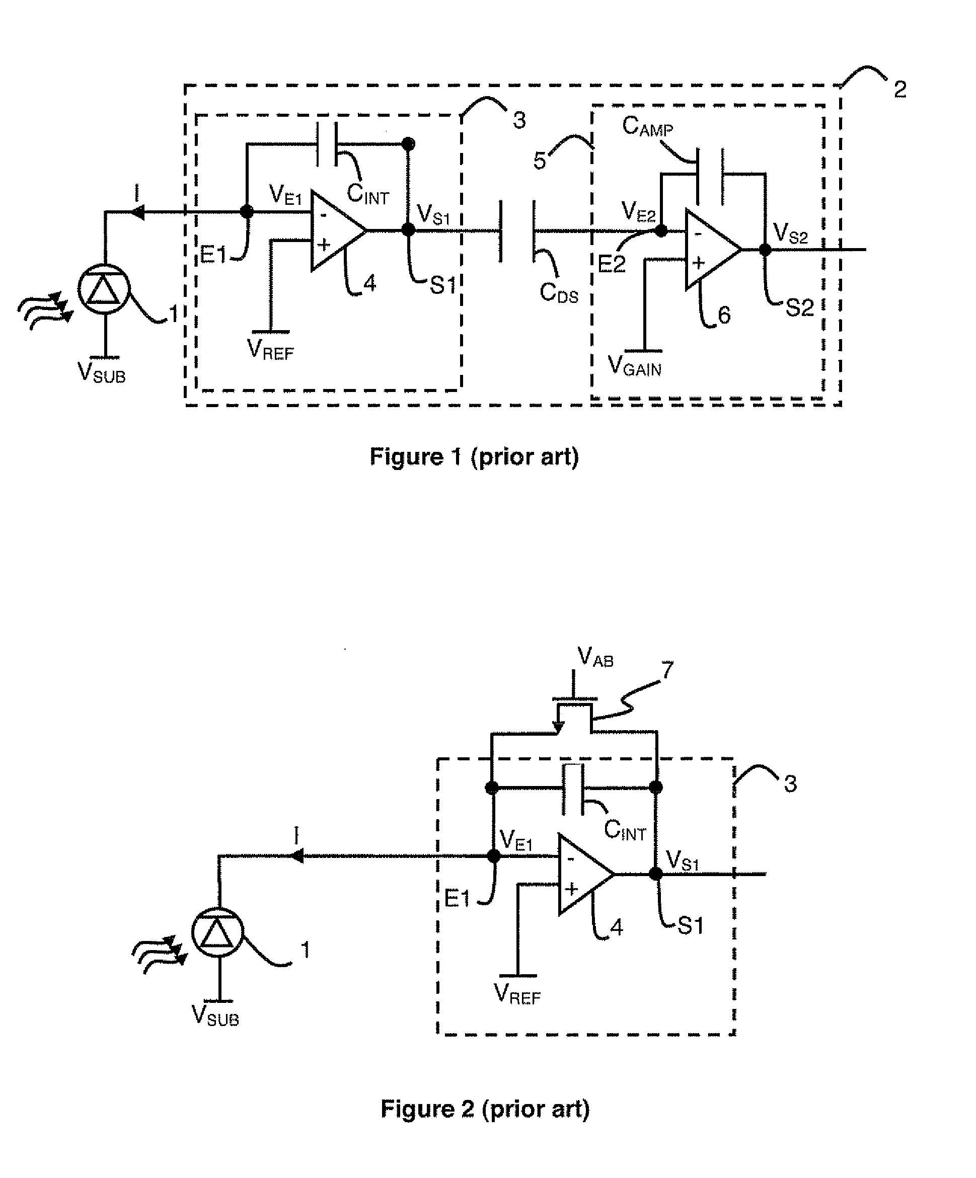
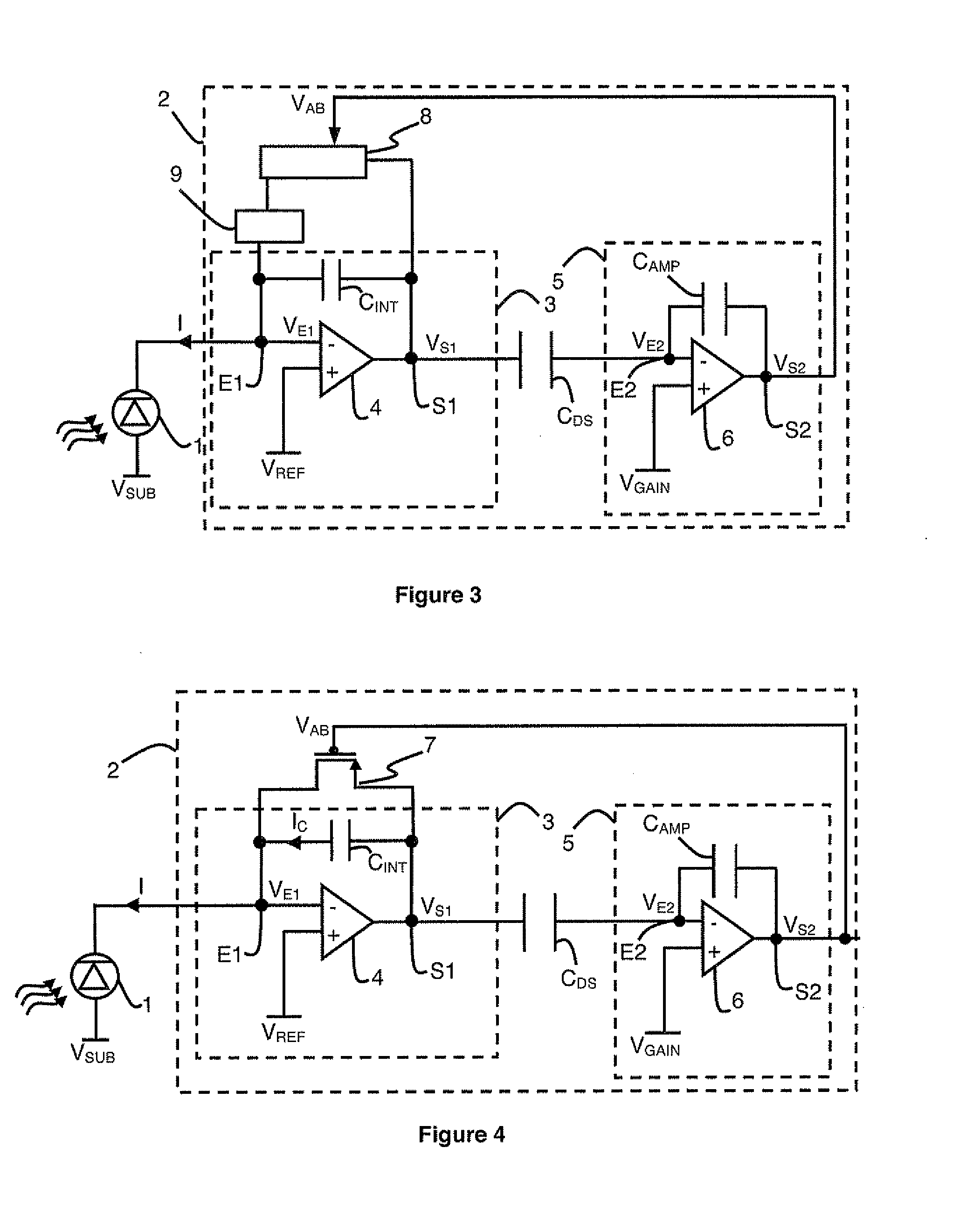
[0034]As illustrated in FIGS. 3 to 5, the detection circuit comprises a photodiode 1 connected to a readout module 2.

[0035]In the detection circuit illustrated in FIGS. 3 to 5, readout module 2 comprises a first transimpedance amplifier 3 and a second transimpedance amplifier 5. The transimpedance amplifiers comprise an amplifier, typically an operational amplifier, and a passive element connected in negative feedback manner, here a capacitor. The capacitor is connected between the first input and the output of the amplifier.

[0036]First capacitive transimpedance amplifier 3 is part of or forms a first integrator module of the detection circuit. Second capacitive transimpedance amplifier 5 is part of or forms a second integrator module of the detection circuit.

[0037]First 3 and second 5 capacitive transimpedance amplifiers are of opposite types. There is one amplifier whose differential pair on input of the circuit is achieved by means of nMOS transistors, and one amplifier whose dif...


PUM


Abstract

The detection circuit with correlated double sampling comprises two transimpedance amplifiers connected by means of a sampling capacitor. A photodiode is connected to the input of the first transimpedance amplifier. The circuit comprises an anti-blooming circuit connected between the input and output of the first transimpedance amplifier. The anti-blooming circuit comprises means for comparing the output voltage of the first transimpedance amplifier with a setpoint voltage defined by means of the output voltage of the second transimpedance amplifier. The means for comparing are connected to means for applying a feedback current to the input of the first transimpedance amplifier when the difference between the output voltage and the setpoint voltage reaches a limit value.

Description

BACKGROUND OF THE INVENTION[0001]The invention relates to a detection circuit with correlated double sampling comprising:[0002]a first transimpedance amplifier,[0003]a photodiode connected to an input of the first transimpedance amplifier,[0004]a second transimpedance amplifier,[0005]a sampling capacitor connected between an output of the first transimpedance amplifier and an input of the second transimpedance amplifier.[0006]The invention also relates to a method for reading the irradiation by a detection circuit.STATE OF THE ART[0007]As illustrated in FIG. 1, in conventional detection circuits, a reverse biased photodiode 1 delivers a current representative of an observed scene. The photodiode 1 delivers this current to a readout module 2 during a predefined period.[0008]Readout module 2 comprises a first integrator device 3 which is formed by a capacitive transimpedance amplifier. The capacitive transimpedance amplifier comprises an amplifier 4 connected in negative feedback mann...

Claims


Application Information

Patent Timeline
IPC IPC(8): H03F3/08
CPCH04N5/3745H04N5/3591H04N5/374H04N25/621H04N25/76H04N25/77
Inventor RICARD, NICOLASSALVETTI, FREDERIC
Owner LYNRED
Why Eureka
Try Eureka