Hydrogen separation alloy and method for producing same

a technology of hydrogen separation and alloy, applied in the direction of hydrogen separation using solid contact, membrane technology, membranes, etc., can solve the problems of high cost of current technical levels, inability to meet the growing demand of pd—ag alloy membrane, etc., to improve hydrogen permeability, improve hydrogen permeability, and improve the effect of hydrogen permeability

Inactive Publication Date: 2012-06-07
HITACHI METALS LTD
View PDF4 Cites 3 Cited by
  • Summary
  • Abstract
  • Description
  • Claims
  • Application Information

AI Technical Summary

Benefits of technology

[0021]The present invention allows an alloy to have a fine layered structure of an elongated hydrogen-permeable phase, to have improved hydrogen-embrittlement resistance by relaxing stress caused by expansion and shrinkage of its crystal lattice with hydrogen absorption / desorption, and to have improved hydrogen permeability.
[0022]As a result, the present invention enables inexpensive production of a hydrogen separation alloy which excels both in hydrogen permeability and in hydrogen-embrittlement resistance and which is adaptable even to a large-sized product having a large surface area of a hydrogen-permeating surface.

Problems solved by technology

This technique, however, costs too much at current technical levels, and hydrogen production is therefore currently mainly performed by reforming of fossil resources.
However, it is predicted that the Pd—Ag alloy membrane does not satisfy growing demands made upon wider usage of fuel cells in future, because expensive and rare Pd poses limitations to the use of Pd—Ag alloy membrane.

Method used


Image

  • Hydrogen separation alloy and method for producing same
  • Hydrogen separation alloy and method for producing same
  • Hydrogen separation alloy and method for producing same

Examples


examples

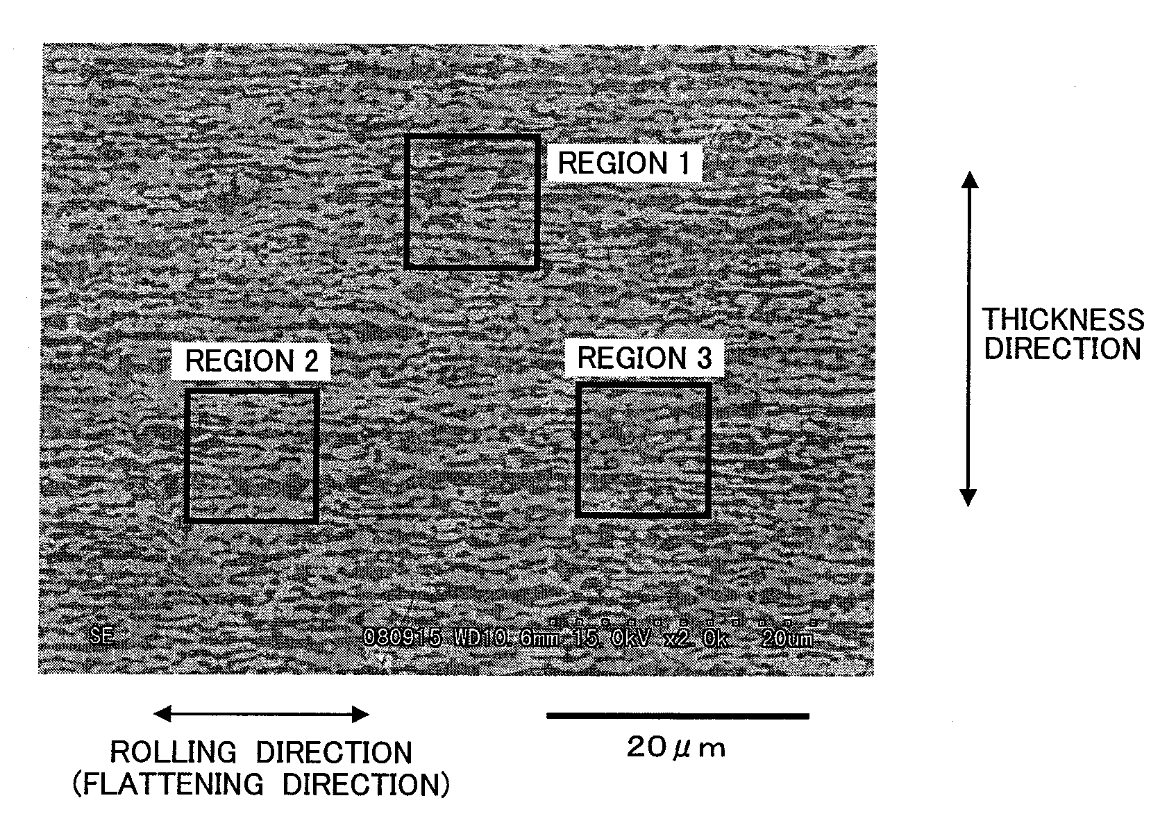
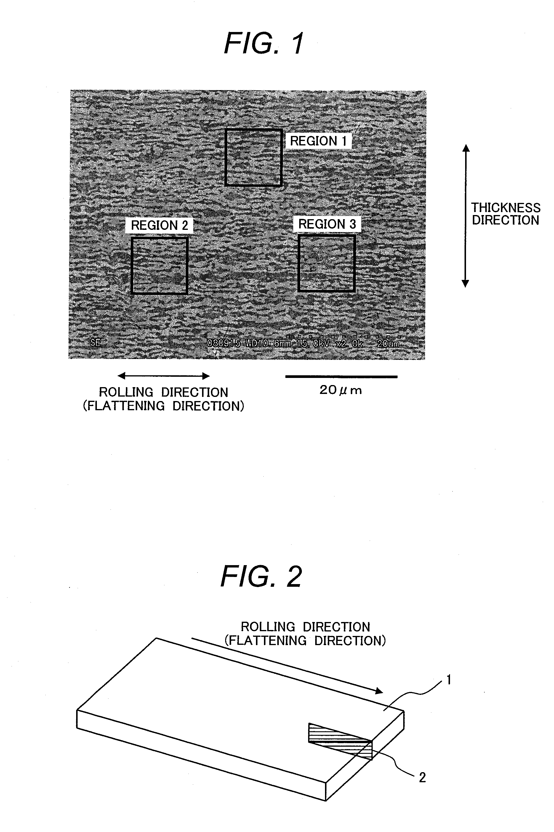
[0037]FIG. 1 depicts an electron micrograph illustrating a cross section of a hydrogen separation alloy according to an embodiment.

[0038]When a cross section in a rolling direction is observed with an electron microscope, the hydrogen separation alloy according to the embodiment has a metallographic structure which is biphasically separated into two phases, i.e., an Nb-enriched white hydrogen-permeable phase and a transition-metal-containing gray hydrogen-embrittlement-resistant phase, for example, as illustrated in the cross sectional electron micrograph of FIG. 1. In the structure, the hydrogen-permeable phase is elongated as a result of plastic working. As used herein the term “transition metal phase” refers to a phase containing two or more transition metal elements belonging to elements of from Group 3 to Group 12 of the periodic table.

[0039]In the hydrogen separation alloy according to the embodiment, the hydrogen-permeable phase should occupy 35 to 70 percent by area of the a...


PUM

PropertyMeasurementUnit
thicknessaaaaaaaaaa
temperatureaaaaaaaaaa

Abstract

Disclosed is a hydrogen separation alloy which is adoptable to a product having a large surface area of a side where hydrogen permeates and which has such a metallographic structure as to improve hydrogen permeability and to improve hydrogen-embrittlement resistance. The hydrogen separation alloy used herein is represented by the compositional formula: Nb100−(α+β)M1αM2β where M1 is at least one element selected from the group consisting of Ti, Zr and Hf; M2 is at least one element selected from the group consisting of Ni, Co, Cr, Fe, Cu and Zn; 10≦α≦60, 10≦β≦50, and α+β≦80. The alloy contains inevitable impurities. And the alloy includes two phases, i.e., an Nb-M1 phase serving as a hydrogen-permeable phase, and a M2-M1 phase serving as a hydrogen-embrittlement-resistant phase. The hydrogen-permeable phase and the hydrogen-embrittlement-resistant phase have an elongated structure resulting from rolling. The hydrogen-permeable phase occupies 35% to 70% of an arbitrary 10 μm×10 μm region in a 50 μm×50 μm observation plane of a cross section of the alloy under an electron microscopic observation, the cross section is taken in a direction of thickness reduced by the rolling and in a direction of rolling and flattening.

Description

TECHNICAL FIELD[0001]The present invention relates to a hydrogen separation alloy to be used for obtaining high-purity hydrogen, and a method for producing the same.BACKGROUND ART[0002]Fuel cells have recently received attention as clean energy. Hydrogen gas serving as a fuel for the fuel cells is not present in a large amount in nature and should be generated artificially.[0003]As one of processes for the hydrogen generation, there is a process for preparing hydrogen by electrolysis of water. This technique, however, costs too much at current technical levels, and hydrogen production is therefore currently mainly performed by reforming of fossil resources.[0004]This process, however, gives not only hydrogen but also impurity gases such as CO, CO2 and H2O. Among them, CO poisons electrodes of the fuel cells. To avoid this and to adopt hydrogen obtained by reforming of the fossil resources to fuel cells, hydrogen should be separated and purified from such impurity gases to have a hig...

Claims


Application Information

Patent Timeline
Patent Type & Authority Applications(United States)
IPC IPC(8): C22F1/18C22C27/02
CPCB01D67/0074B01D71/022B01D2323/12B01D2325/04C22C27/02C22F1/16C22F1/18C01B3/503C01B3/505C22F1/00B01D71/02C01B3/56C22C16/00
Inventor YAMAMURA, KAZUHIROTOBISE, MASAHIRO
Owner HITACHI METALS LTD
Why Eureka
Try Eureka