Image forming apparatus and image forming method

Inactive Publication Date: 2012-07-19
KONICA MINOLTA BUSINESS TECH INC
View PDF4 Cites 6 Cited by
  • Summary
  • Abstract
  • Description
  • Claims
  • Application Information

AI Technical Summary

Benefits of technology

[0008]In view of the problems described above, it is an object of the present invention to provide an image forming apparatus and image forming

Problems solved by technology

In the image forming method proposed in the Japanese Patent Application Publication No. 2009-58738, however, the following problem arises when the envelope is conveyed with the flap portion located downstream in t

Method used


Image

  • Image forming apparatus and image forming method
  • Image forming apparatus and image forming method
  • Image forming apparatus and image forming method

Examples


Embodiment Construction

[0033]The following describes an example of the image forming apparatus and image forming method related to the embodiment of the present invention with reference to drawings.

[0034][Structure of an Image Forming Apparatus]

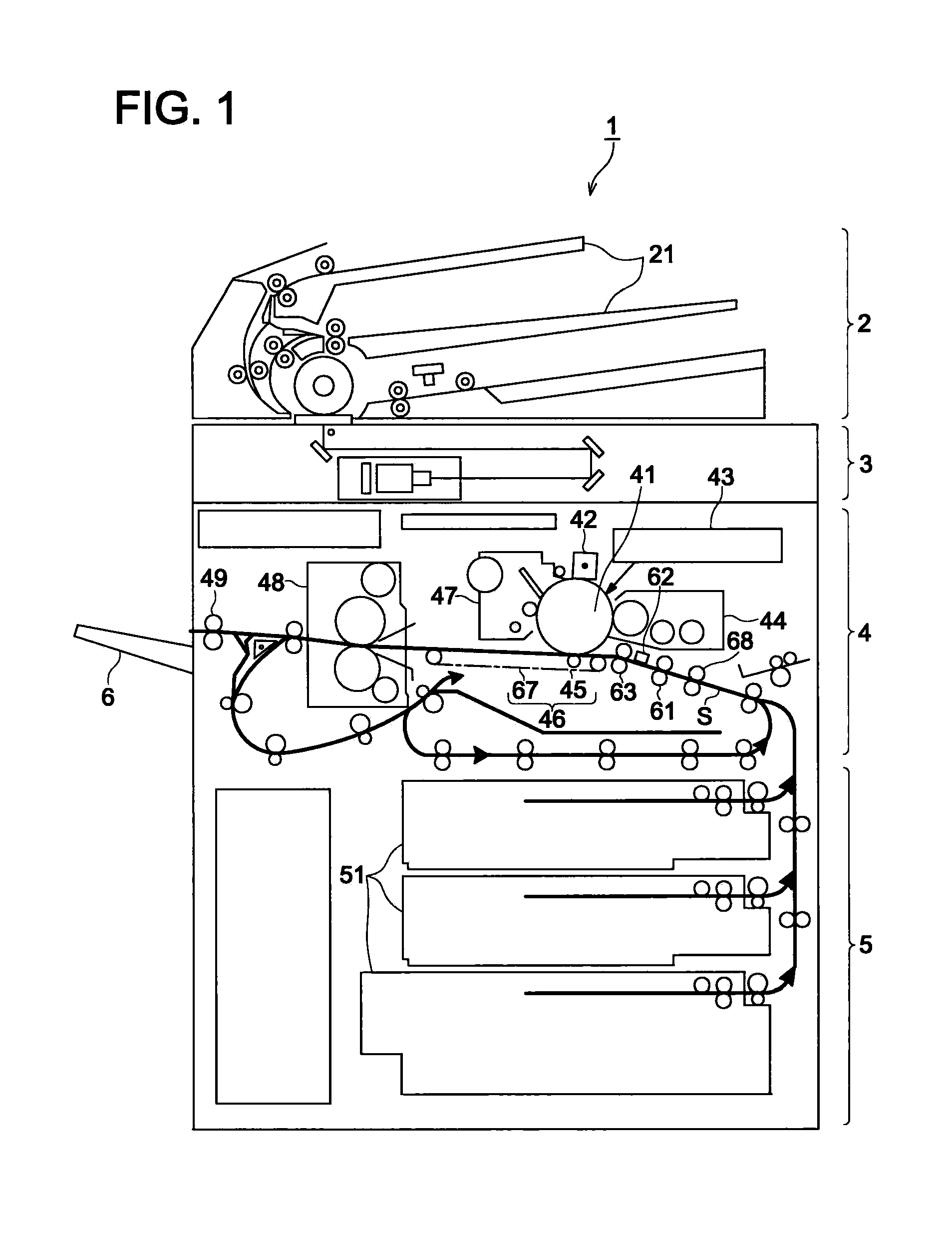
[0035]FIG. 1 is a schematic cross sectional view representing an image forming apparatus in an embodiment of the present invention. FIG. 1 shows an example of the structure of the image forming apparatus 1 provided with functions of a photocopier, printer, facsimile and other to form a monochromatic image on a sheet of paper by means of an electrophotographic process.

[0036]The image forming apparatus 1 includes a document feed section 2, document reading section 3, image forming section 4, sheet feed section 5 and sheet ejection tray 6. The image forming apparatus 1 incorporates sheet conveyance path S leading from the sheet feed section 5 to the sheet ejection tray 6 through the image forming section 4. This sheet conveyance path S is formed of various rollers, g...


PUM


Abstract

An image forming apparatus includes: a registration roller which corrects a skew of the envelope and conveys the envelope to the transferring section; a sensor provided between a transferring section and the registration roller wherein in a case when an envelope is conveyed with a side of the main body thereof having the flap portion being parallel to the conveying direction and the flap portion being located where the end detected is by the sensor, a controller allows the sensor to detect a position of the end of the parallel portion of the flap portion when the registration roller and the sensor are located at the parallel portion of the flap portion, and the controller changes a latent image writing position by the writing section in an image scanning direction perpendicular to the conveyance direction of the envelope according to the detection result by the sensor

Description

[0001]This application is based on Japanese Patent Application Nos. 2011-006533 filed on Jan. 17, 2011 and 2011-231620 filed on Oct. 21, 2011, which is incorporated hereinto by reference.BACKGROUND OF THE INVENTION[0002]The present invention relates to an image forming apparatus for forming an image on an envelope and a method for forming this image.[0003]Some of the conventional image forming apparatuses such as photocopiers, printers and facsimiles have a function of forming an image on an envelope.[0004]Differently from plain paper, an envelope has a flap portion on the and thereof to be used for pasting. Thus, in a proposal of a method for forming an image on the envelope, consideration is given to the flap portion (e.g., Japanese Patent Application Publication No. 2009-58738).[0005]In the proposal disclosed in the Japanese Patent Application Publication No. 2009-58738, when the envelope is fed with the flap portion located downstream in the sheet conveying direction, the image ...

Claims


Application Information

Patent Timeline
IPC IPC(8): G03G15/00
CPCG03G15/5029G03G15/6567G03G15/6594G03G15/235G03G2215/00599G03G2215/0426G03G2215/00514
Inventor OMORI, YUICHI
Owner KONICA MINOLTA BUSINESS TECH INC
Why Eureka
Try Eureka