Antenna Support Structure For Magnetic Resonance Imaging

a technology of magnetic resonance imaging and support structure, which is applied in the field of anti-antenna support structure for magnetic resonance imaging, can solve the problems of not always properly sized coils for patients, unique challenges of pediatric patients' mris, and cost prohibitive for some imaging centers to maintain pediatric imaging assemblies, etc., to achieve the effect of improving imaging of pediatric patients

Active Publication Date: 2012-10-18
NEOCOIL
View PDF4 Cites 10 Cited by
  • Summary
  • Abstract
  • Description
  • Claims
  • Application Information

AI Technical Summary

Benefits of technology

[0005]Thus, it would be desirable to provide a MRI imaging assembly adaptable to varying sizes of patients and easily accessible to enhance imaging of pediatric patients.

Problems solved by technology

As is known to those skilled in the art, obtaining MRIs of pediatric patients presents unique challenges.
Because pediatric patients are generally smaller in size and present greater variation in the size of patients than adults, coils are not always properly sized for the patient.
Further, due to the expense of coils and due to the majority of MRI patients being adults, it may be cost prohibitive for some imaging centers to maintain pediatric imaging assemblies.
Such systems limit the use of non-uniform shapes that must fit inside the predefined contour of the coil.

Method used


Image

  • Antenna Support Structure For Magnetic Resonance Imaging
  • Antenna Support Structure For Magnetic Resonance Imaging
  • Antenna Support Structure For Magnetic Resonance Imaging

Examples


Embodiment Construction

[0071]The various features and advantageous details of the subject matter disclosed herein are explained more fully with reference to the non-limiting embodiments described in detail in the following description.

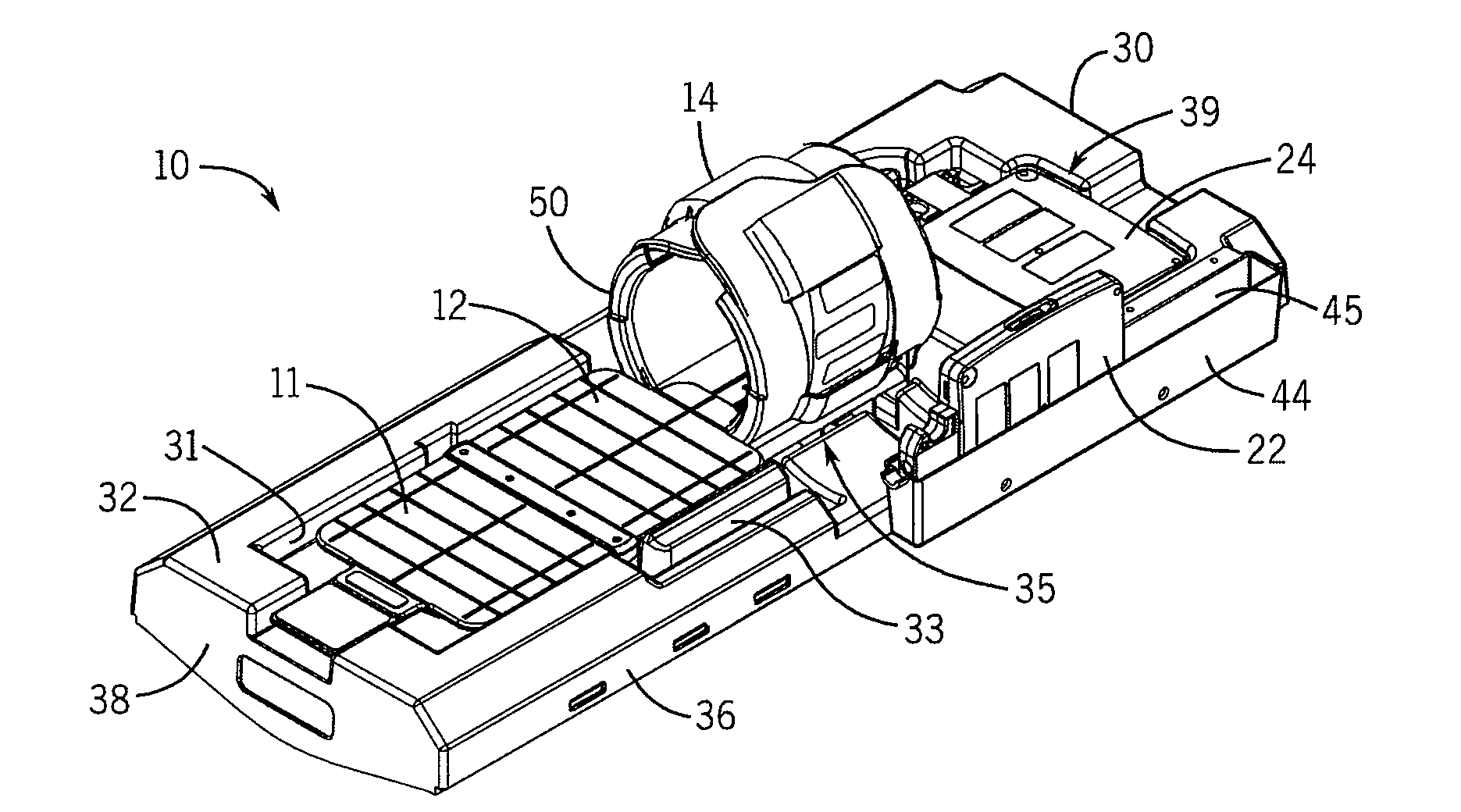
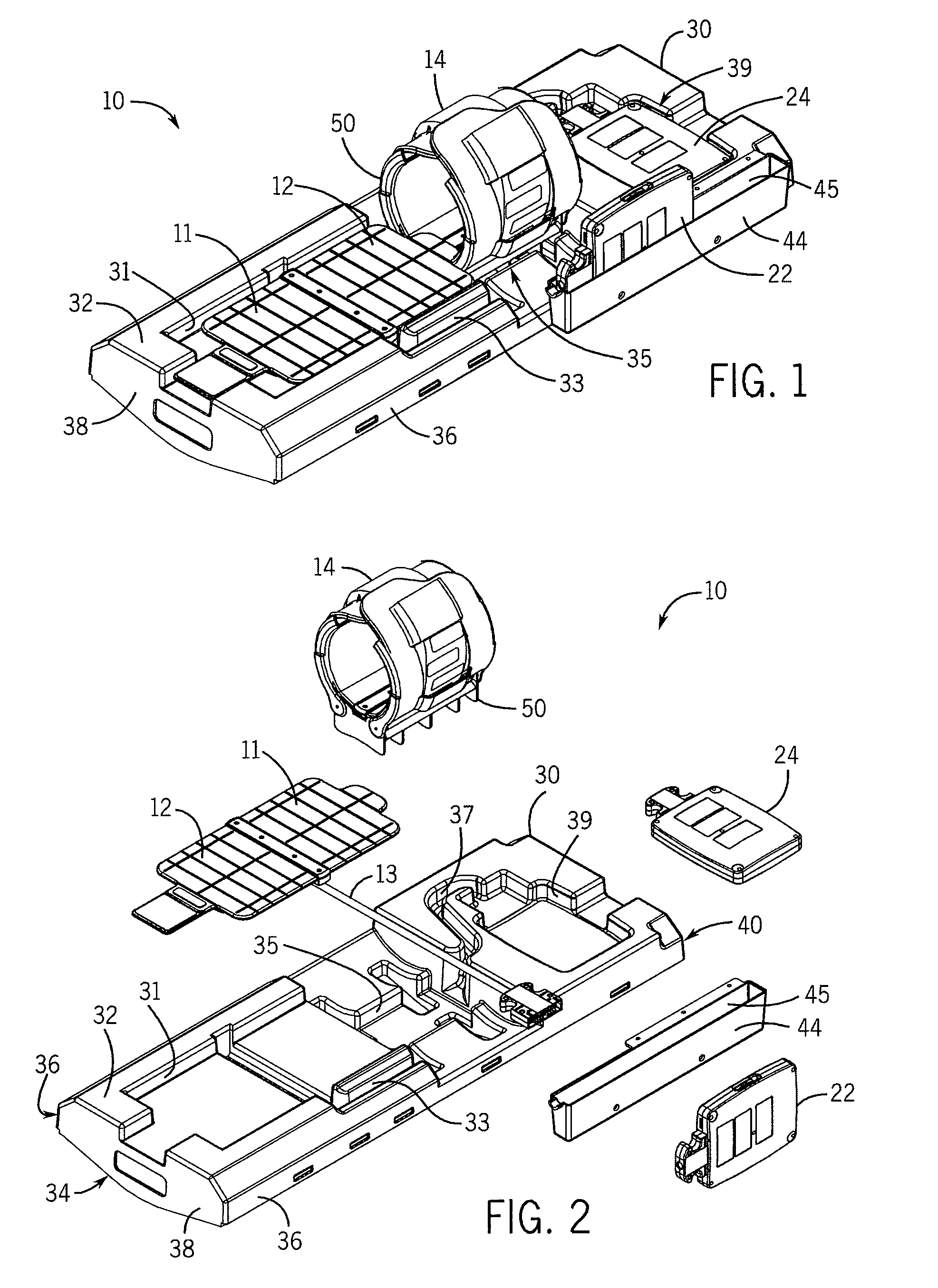
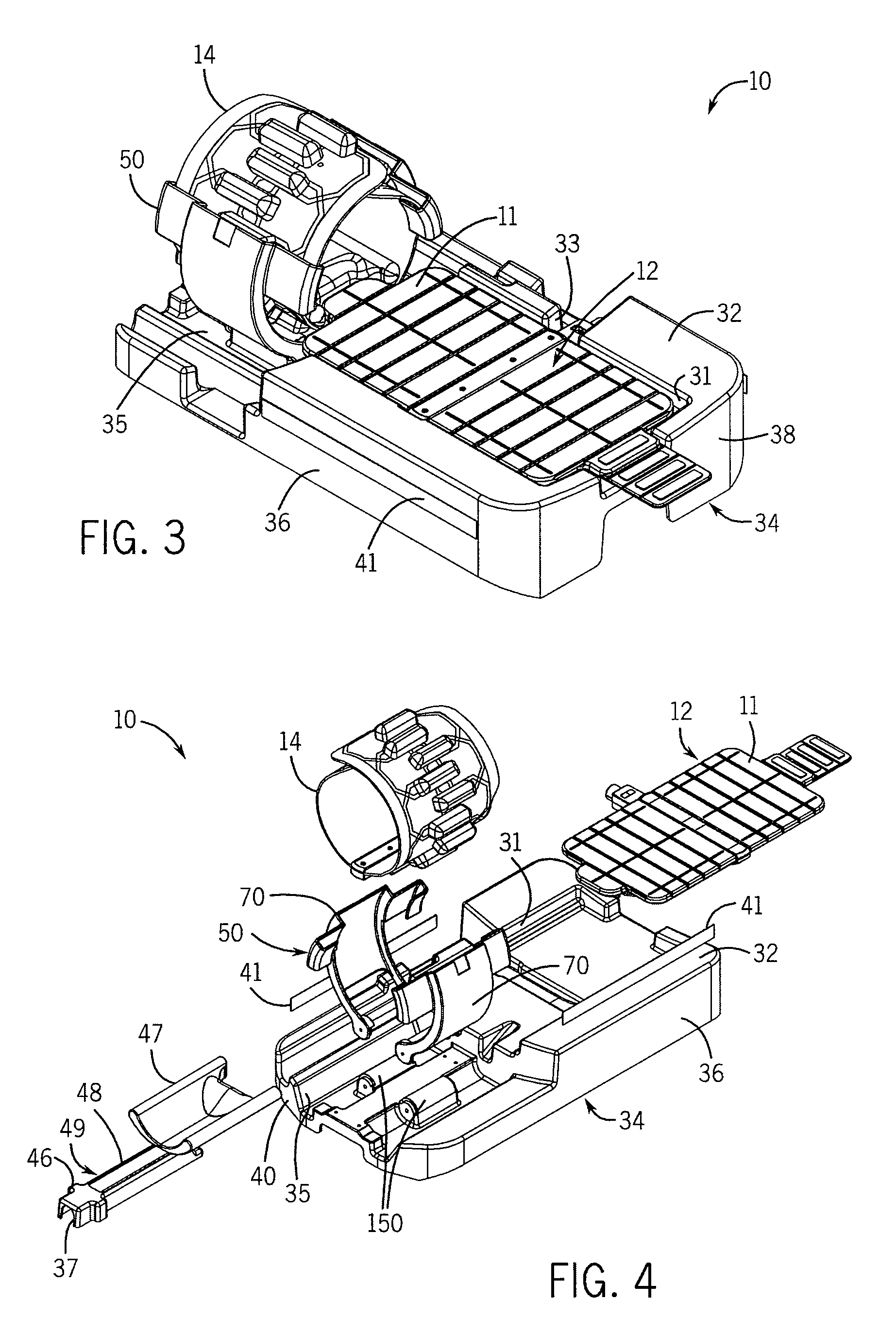
[0072]Turning initially to FIGS. 1 and 2, one embodiment of a patient support assembly 10 includes at least one patient stabilization structure used to position a patient within a MRI scanner. According to the illustrated embodiment, a first patient support 30 includes a top surface 32, a bottom surface 34, and multiple side walls 36, a front wall 38, and a rear wall 40 joining the top surface 32 and the bottom surface 34. The first patient support 30 may be a single molded assembly or, optionally, may include two or more components joined to form the first patient support 30.

[0073]The top surface 32 includes a first recess 31 configured to receive a first antenna array 12. The antenna array 12 may be, for example, an antenna array as provided by applicant and described in U...


PUM


Abstract

A patient support structure for use in a magnetic resonance image (MRI) scanner includes a base and a first and a second arm pivotally connected to the base. The patient support structure supports an anatomical region being imaged and positions an antenna array around the anatomical region. Access to the patient is improved by: providing a flexible coil that wraps around the anatomical region being imaged, providing a support structure open to the anterior region of the anatomical region being imaged, and providing a support structure that may be opened and closed about the anatomical region being imaged.

Description

CROSS-REFERENCE TO RELATED APPLICATIONS[0001]This application claims priority to U.S. provisional application Ser. No. 61 / 475,884, filed Apr. 15, 2011, entitled Pediatric Imaging Assembly, the entire contents of which is incorporated herein by reference.BACKGROUND OF THE INVENTION[0002]The subject matter disclosed herein relates to a system for use in obtaining a magnetic resonance image (MRI) of a pediatric patient. More specifically, the assembly includes support structures both for patient comfort and stability as well as structures to position antenna arrays with respect to the patient.[0003]As is known to those skilled in the art, obtaining MRIs of pediatric patients presents unique challenges. The quality of images obtained in MRI scanners is in part, a function of the location of the antenna array with respect to the anatomical region being images. Currently, most imaging systems are of a rigid or fixed construction, requiring different coils to be used for patients of differ...

Claims


Application Information

Patent Timeline
Patent Type & Authority Applications(United States)
IPC IPC(8): A61B5/055
CPCA61B5/0042A61B5/0555A61B2503/06G01R33/3415G01R33/34046A61B5/055G01R33/34007A61G13/121A61G2210/50G01R33/30
Inventor ROHR, ROBERT D.SALIMES, CHRISTOPHERWAGNER, LESLIEGORUGANTI, VENKATBROWN, BRIAN
Owner NEOCOIL
Why Eureka
Try Eureka