Laryngoscope and Method of Use

a technology of laryngoscope and tracheal tube, which is applied in the field of laryngoscope and laryngoscope, can solve the problems of additional harm or death for patients, difficult laryngoscope viewing, etc., and achieve the effects of enhancing color, enhancing visualization of vocal cords, and enhancing visualization of endotracheal tubes passing through vocal cords

Active Publication Date: 2012-12-27
SALTER LABS LLC
View PDF10 Cites 37 Cited by
  • Summary
  • Abstract
  • Description
  • Claims
  • Application Information

AI Technical Summary

Benefits of technology

[0004]To solve these problems and others, an aspect of present invention involves a laryngoscope including an improved light source. The laryngoscope blade carries a black light source that emits a black light during laryngoscopy. The black light enhances visualization of the vocal cords so that visualization of the endotracheal tube passing through the vocal cords is enhanced. The black light emitted from the laryngoscope enhances colors that are white and / or contain phosphors in the region of the vocal cords, enhancing visualization of the target vocal cords. In another implementation of the laryngoscope, the laryngoscope blade carries a black light source and a white light source. A switch on the laryngoscope enables the health care provider to actuate the black light source, the white light source, or to activate both light sources.

Problems solved by technology

Even with a light source on the laryngoscope blade, viewing of the vocal cords has still proven difficult during laryngoscopy.
Accordingly, without the ability to view the vocal cords, many possible laryngoscopy procedures are not performed successfully, resulting in additional harm or death for the patient.

Method used


Image

  • Laryngoscope and Method of Use
  • Laryngoscope and Method of Use
  • Laryngoscope and Method of Use

Examples


Embodiment Construction

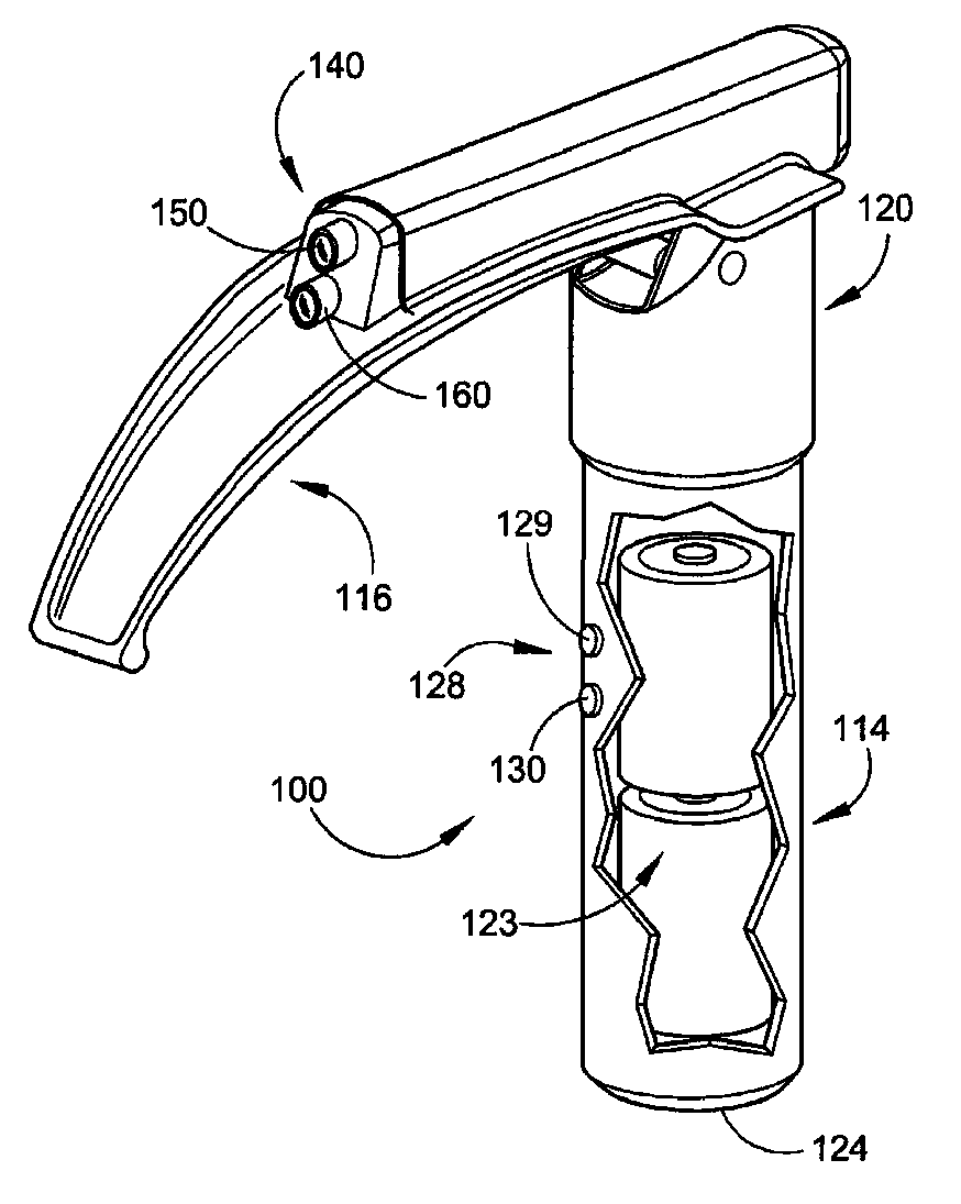
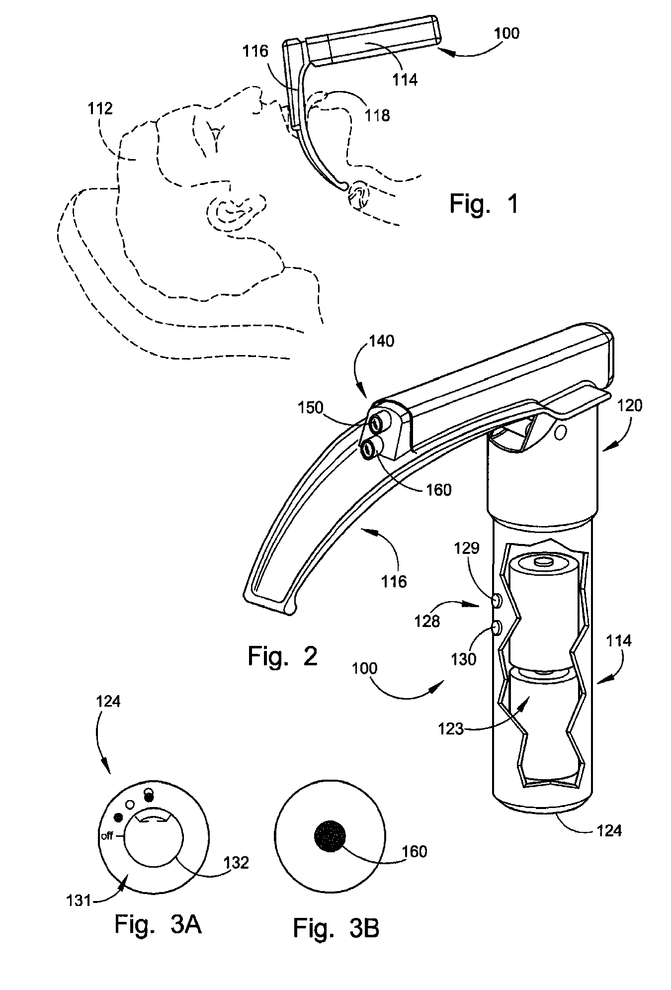
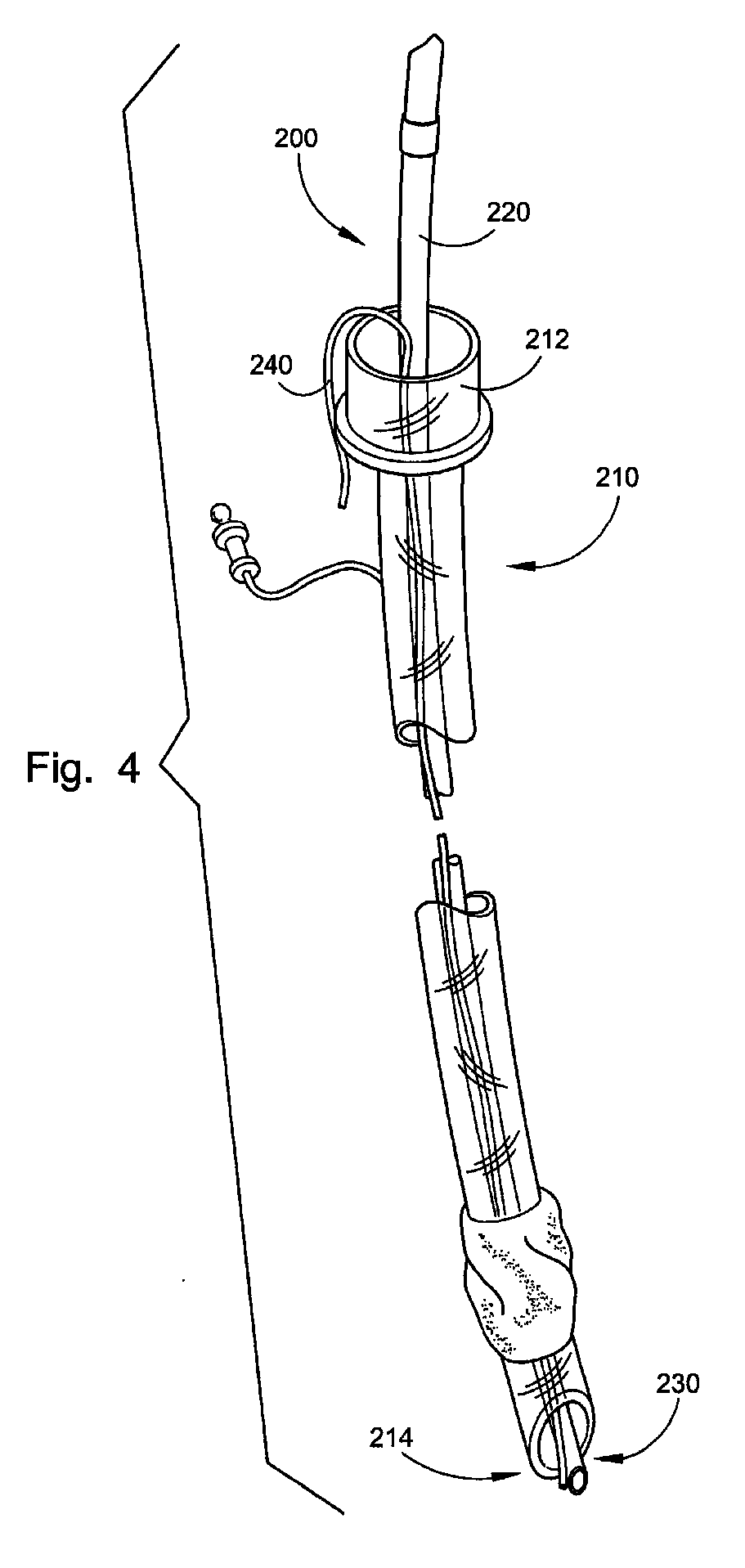
[0086]With reference to FIGS. 1 and 2, a laryngoscope 100 constructed in accordance with an embodiment of the invention will be described. In FIG. 1, the laryngoscope 100 is shown placed in the mouth of a patient 112 for viewing the vocal cords adjacent the larynx and to aid in the insertion of an endotracheal tube 200 (FIG. 4) past the vocal cords. The laryngoscope 100 includes a handle or handgrip 114 and a blade portion 116, the latter being used to lift the tongue and mandible 118 out of the way for viewing the vocal cords.

[0087]As shown in FIG. 2, the blade portion 116 is pivotally connected to a handle cap 120. The blade portion 116, the handle cap 120, and the handle 114 can be readily assembled together for use. In the embodiment shown, when assembled, a white light source 150 and a black light source 160 are automatically actuated. In an alternative embodiment, the blade portion 116 is directly connected to a top of the handle 114 (i.e., there is no handle cap). The handle ...


PUM


Abstract

A laryngoscope device for use in the performance of direct laryngoscopy, the device including a laryngoscope blade portion connectable to a laryngoscope handle through a connector, the laryngoscope blade comprising an ultraviolet light, a white light and an imaging or viewing device at the same distance relative to the distal end of the laryngoscope blade.

Description

CROSS-REFERENCE TO RELATED APPLICATIONS[0001]This application is a continuation-in-part of U.S. patent application Ser. No. 13 / 290,792, filed on Nov. 7, 2011, which is a continuation of U.S. patent application Ser. No. 12 / 698,467, filed Feb. 2, 2010, which is a continuation-in-part of U.S. patent application Ser. No. 29 / 346,594, filed Nov. 3, 2009, now U.S. Des. Pat. Number D632,787, and is a continuation-in-part of U.S. patent application Ser. No. 12 / 368,952, filed Feb. 10, 2009, now abandoned, which is a continuation-in-part of U.S. patent application Ser. No. 12 / 173,961, filed on Jul. 16, 2008, now U.S. Pat. No. 8,012,087, which is a continuation-in-part of U.S. patent application Ser. No. 12 / 144,147, filed Jun. 23, 2008. This application also claims priority under 35 U.S.C. 119(e) to U.S. Provisional Patent Application No. 61 / 288,779, filed Dec. 21, 2009. The contents of each and all of the above patent applications are incorporated herein by reference in their entirety.FIELD OF...

Claims


Application Information

Patent Timeline
Patent Type & Authority Applications(United States)
IPC IPC(8): A61B1/267A61B1/06A61B1/04
CPCA61B1/043A61B1/0638A61M16/04A61B1/0684A61B1/2673A61B1/0676A61M16/0427A61M16/0429A61M16/0495
Inventor TENGER, JAMES P.TENGER, LESLIE A.HICKS, JOHN R.
Owner SALTER LABS LLC
Why Eureka
Try Eureka