Fuel cooling system for dimethyl-ether fuel vehicle

a technology of dimethyl ether and fuel vehicles, applied in the field of cooling systems, can solve the problems of reducing and releasing a large amount of particulate materials (pm) and nitride oxides, etc., and achieve the effect of improving the cooling effect of the fuel cooling devi

Inactive Publication Date: 2013-02-07
HYUNDAI MOTOR CO LTD
View PDF18 Cites 7 Cited by
  • Summary
  • Abstract
  • Description
  • Claims
  • Application Information

AI Technical Summary

Benefits of technology

[0016]Various aspects of the present invention are directed to implement a system that enhances cooling effect of a fuel cooling device by collecting cold condensed water produced in an evaporator of an air conditioner.

Problems solved by technology

In general, a diesel engine used in vehicles has an advantage of having high thermal efficiency and discharging a small amount of carbon dioxide that is a gas causing global warming in comparison to other engines, but has a problem in that it discharges a large amount of particulate materials (PM) and nitride oxides (NOx).
Accordingly, although using a natural gas and liquefied petroleum gas (LPG), as a low-air pollution substitute fuel for the diesel engine, has been actively promoted, there is a problem in that thermal efficiency decreases in comparison to the diesel engine and it is required to reconstruct many parts, including the fuel system, such that dimethyl-ether (DME) has drawn considerable attention as a substitute fuel for the diesel engine.
However, in a season with high external temperature, such as in summer, the cooling effect of a fuel cooling device decreases, the cooling device frequently operates, and the durability and fuel efficiency decrease.

Method used


Image

  • Fuel cooling system for dimethyl-ether fuel vehicle
  • Fuel cooling system for dimethyl-ether fuel vehicle
  • Fuel cooling system for dimethyl-ether fuel vehicle

Examples


Embodiment Construction

[0029]Reference will now be made in detail to various embodiments of the present invention(s), examples of which are illustrated in the accompanying drawings and described below. While the invention(s) will be described in conjunction with exemplary embodiments, it will be understood that present description is not intended to limit the invention(s) to those exemplary embodiments. On the contrary, the invention(s) is / are intended to cover not only the exemplary embodiments, but also various alternatives, modifications, equivalents and other embodiments, which may be included within the spirit and scope of the invention as defined by the appended claims.

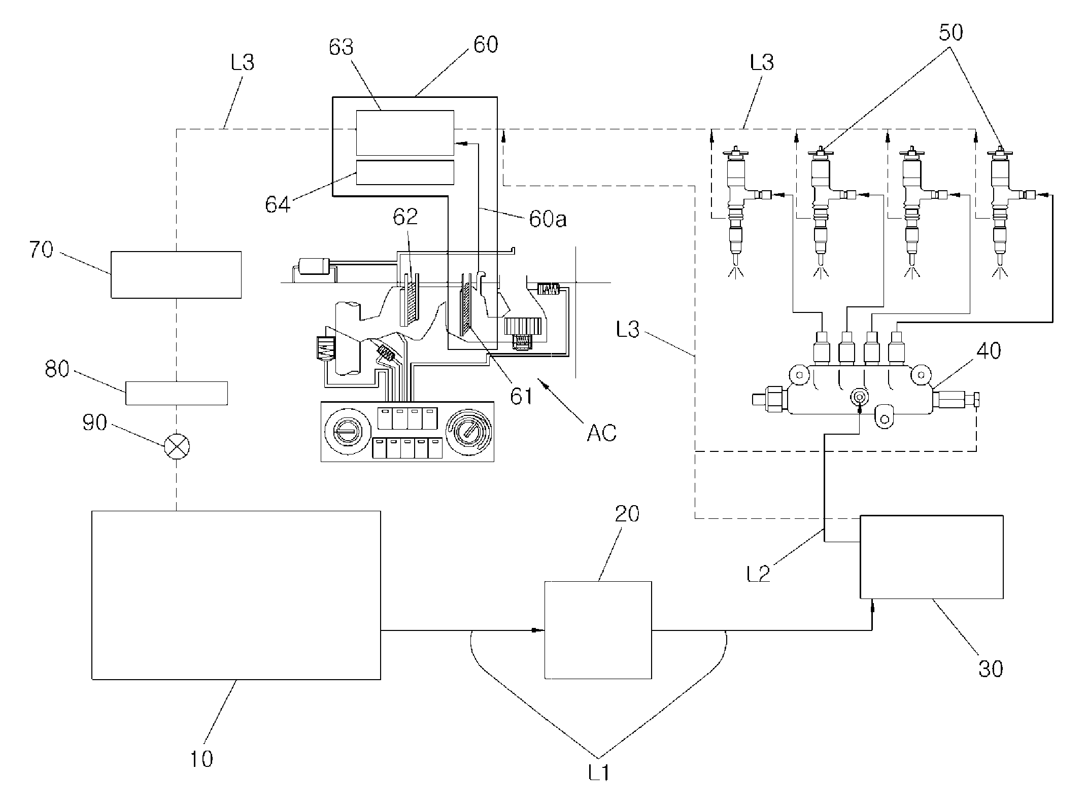
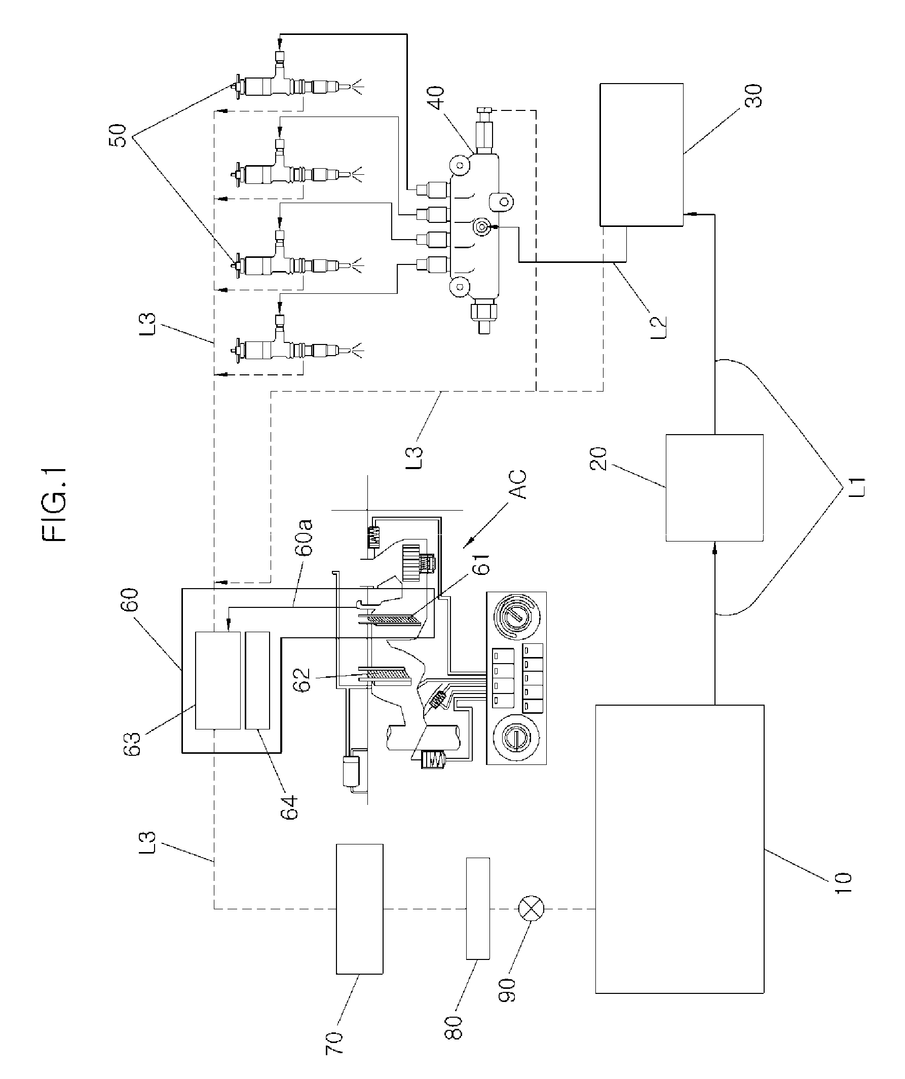
[0030]Referring to FIG. 1, the fuel cooling system for a dimethyl-ether (DME) fuel vehicle according to various embodiments of the present invention includes a fuel tank 10, a fuel supply pipe L1, a low-pressure pump 20, a high-pressure pump 30, a common rail 40, a fuel injection system 50, a fuel cooling device 60, an accumulator 70,...


PUM


Abstract

A fuel cooling system for a dimethyl-ether fuel vehicle includes a fuel tank storing dimethyl-ether, a fuel supply line introducing the dimethyl-ether into an engine, a fuel supply pump, pressurizing the dimethyl-ether, and sending the pressurized dimethyl-ether to a fuel injection system, a common rail maintaining a pressure of the pressurized dimethyl-ether from the fuel supply pump, a fuel injection system injecting the pressurized dimethyl-ether supplied from the common rail, a fuel return line communicating with and diverging from the fuel injection system, the common rail and/or a downstream side of the fuel supply pump to collect remaining dimethyl-ether, a fuel cooling device disposed in the fuel return line, and a drain pipe to discharge condensed water generated from an evaporator disposed in an air conditioner, wherein discharged condensed water from the drain pipe is supplied to the fuel cooling device and cools the collected dimethyl-ether.

Description

CROSS-REFERENCE TO RELATED APPLICATIONS[0001]The present application claims priority of Korean Patent Application Number 10-2011-0076699 filed Aug. 1, 2011, the entire contents of which application are incorporated herein for all purposes by this reference.BACKGROUND OF INVENTION[0002]1. Field of Invention[0003]The present invention relates to a cooling system, and more particularly, to a fuel cooling system of a dimethyl-ether (DME) fuel vehicle that can optimize fuel cooling performance of the DME fuel vehicle, in which the DME has been developed as a substitute energy.[0004]2. Description of Related Art[0005]In general, a diesel engine used in vehicles has an advantage of having high thermal efficiency and discharging a small amount of carbon dioxide that is a gas causing global warming in comparison to other engines, but has a problem in that it discharges a large amount of particulate materials (PM) and nitride oxides (NOx).[0006]Accordingly, although using a natural gas and li...

Claims


Application Information

Patent Timeline
Patent Type & Authority Applications(United States)
IPC IPC(8): F02M69/46
CPCF01P2060/10Y02T10/126F02M33/08F02M31/20Y02T10/12F02M21/02F02M37/00F02M55/04
Inventor JANG, JONGMIN
Owner HYUNDAI MOTOR CO LTD
Why Eureka
Try Eureka