Illumination unit and display apparatus using the same

a technology of display apparatus and illumination unit, which is applied in the direction of lighting and heating apparatus, planar/plate-like light guides, instruments, etc., can solve the problems of uneven brightness, difficulty in suitably reducing such an uneven brightness, and local increase of light intensity, so as to reduce uneven brightness

Active Publication Date: 2013-02-28
MAXELL HLDG LTD
View PDF5 Cites 1 Cited by
  • Summary
  • Abstract
  • Description
  • Claims
  • Application Information

AI Technical Summary

Benefits of technology

[0012]According to the present invention, in an illumination unit using LEDs as a light source and a display apparatus using the same, an effect of suitably reducing uneven brightness can be obtained.

Problems solved by technology

Therefore, in the conventional art, it is difficult to suitably reduce such an uneven brightness that the light intensity locally increases in the vicinity of the LED, as described above.
Moreover, in the case where a light source is configured by arranging a plurality of LEDs in a predetermined direction, the light emitted from an LED does not sufficiently reach a portion between the LEDs, and therefore the portion between the LEDs becomes a dark portion that is locally dark, causing uneven brightness.

Method used


Image

  • Illumination unit and display apparatus using the same
  • Illumination unit and display apparatus using the same
  • Illumination unit and display apparatus using the same

Examples


embodiment 1

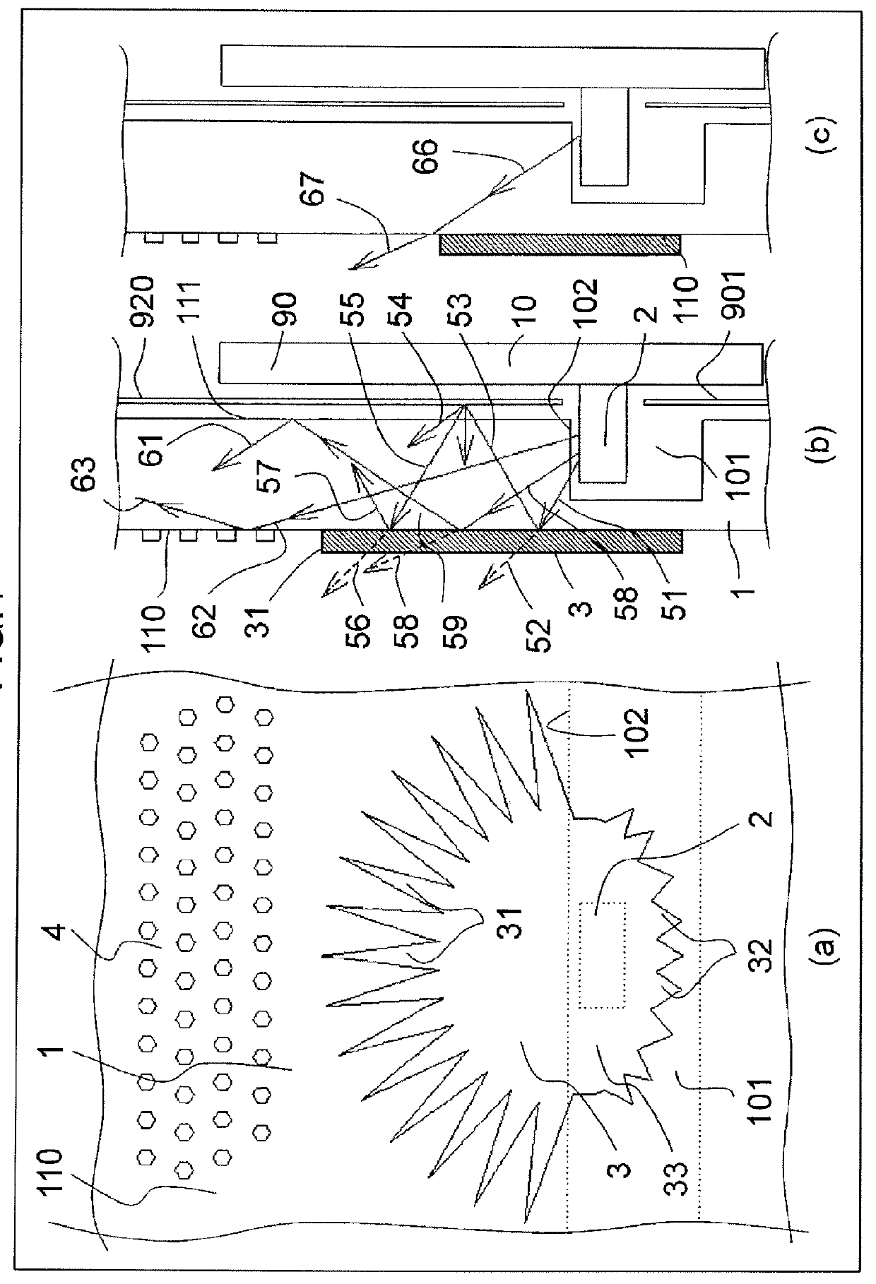
[0028]FIG. 1 is a view for illustrating a dimming pattern 3 and a light guide pattern 4 of a light guide plate 1 and the functions thereof according to a first embodiment of the present invention. The embodiment is characterized in that the dimming pattern 3 with a radial protrusion, e.g., a chestnut-shaped dimming pattern 3, is provided at a portion positionally corresponding to an LED 2 (provided directly above an LED 2) of a light emitting surface 110 of the light guide plate 1 that converts the light from the LED 2 being a light emitting element, to planar light and emits the same. Moreover, the light guide pattern 4 comprising a collection of dots is formed with a predetermined spacing in a light emitting direction of the LED 2 of the dimming pattern 3. The detail of the embodiment is described later. First, detailed description of a display apparatus and an illumination unit, to which the embodiment is applied, is provided referring to FIG. 2 to FIG. 6.

[0029]FIG. 2 is a perspe...

embodiment 2

[0061]Next, a second embodiment of the present invention is described with reference to FIGS. 10A and 10B. The embodiment is the same as the first embodiment in that the LED 2 and the dimming pattern are arranged along the longer direction of a plurality of groove portions 101 as illustrated in FIG. 10A, however, the shape of the dimming pattern differs. A dimming pattern 300 according to the embodiment, as illustrated in FIG. 10A, comprises an elliptic portion 33 covering the LED 2 on the light emitting surface 110 side, emission-side tip protrusions 301 radially extending to the light-emitting side around the location of the LED 2, intermediate protrusions 302 radially extending to the light-emitting side around the location of the LED 2, and rear-side protrusions 303 radially extending to the rear side around the location of the LED 2, and these portions suppress the uneven brightness. In this manner, as with the first embodiment described in FIG. 1, the optical spot is reduced, ...

embodiment 3

[0064]Next, a third embodiment of the present invention is described with reference to FIGS. 11A and 11B. The embodiment is also the same as the first embodiment and the second embodiment in that the LED 2 and the dimming pattern are arranged along the longer direction of a plurality of groove portions 101 as illustrated in FIG. 11A, however, the shape of the dimming pattern, in particular, the shape of the emission-side protrusion and the rear-side protrusion, differ.

[0065]A dimming pattern 310 according to the embodiment, as illustrated in FIGS. 11A and 11B, comprises the elliptic portion 33 covering the LED 2 on the light emitting surface 110 side, emission-side protrusions 311 radially extending to the light-emitting side around the location of the LED 2, and rear-side protrusions 312 radially extending to the rear side around the location of the LED 2, and these portions suppress the uneven brightness. In this manner, as with the first embodiment described in FIG. 1, the optica...


PUM


Abstract

An illumination unit of the present invention includes a tabular light guide plate having a light emitting surface for emitting light coming from an LED as planar light, wherein a recessed portion is formed in the opposite surface of the light emitting surface of the light guide plate, and wherein the LED is provided in the recessed portion so that the optical axis of the LED becomes parallel to the light emitting surface of the light guide plate. Then, a dimming pattern is provided at a location corresponding to the LED of the light emitting surface of the light guide plate, and the dimming pattern includes a main portion covering the LED on the light emitting surface side, and protrusions radially extending toward a light emitting direction of the LED around the LED.

Description

INCORPORATION BY REFERENCE[0001]The present application claims priority from Japanese application JP2011-184273 filed on Aug. 26, 2011, the content of which is hereby incorporated by reference into this application. The contents of Japanese applications JP2011-184274 filed on Aug. 26, 2011 and JP2011-184271 filed on Aug. 26, 2011 are also hereby incorporated by reference into this application.BACKGROUND OF THE INVENTION[0002]The present invention relates to an illumination unit using an LED (Light Emitting Diode) as a light source, and to a display apparatus using the same as a back light.[0003]The illumination unit using LEDs, i.e., light emitting elements, as a light source is used as a back light of a display apparatus with a transmission type display device, such as a liquid crystal display panel (LCD), and is widely put into practical use.[0004]As the configuration of the illumination unit used as a back light, a configuration using an LED as a light source and a light guide pl...

Claims


Application Information

Patent Timeline
Patent Type & Authority Applications(United States)
IPC IPC(8): G09F13/04F21V1/02
CPCG02B6/0018G02B6/0021G02B6/0031G02B6/0078G02B6/0055G02B6/0068G02B6/0073G02B6/0036
Inventor SHIRAISHI, MIKIOTANABE, MASAYUKITANIMURA, MIKAYAMAMOTO, SHOJITAKANO, KENJISHIMANE, YOSHIFUMIOHARA, YASUAKINAKAMURA, REIJI
Owner MAXELL HLDG LTD
Why Eureka
Try Eureka