Antenna Interface for a Radio Receiver

a radio receiver and antenna technology, applied in the direction of antenna connectors, coupling contact members, coupling device connections, etc., can solve the problems of affecting the miniaturization of the receiver, the use of two sockets is relatively bulky,

Inactive Publication Date: 2013-03-21
THALES SA
View PDF5 Cites 5 Cited by
  • Summary
  • Abstract
  • Description
  • Claims
  • Application Information

AI Technical Summary

Benefits of technology

[0005]An objection of the present invention may resolve this drawback, by allowing the connection of an antenna to a dual-band receiver, while limiting the bulk of the connection means.

Problems solved by technology

However, the use of two sockets is relatively bulky, which is in particular detrimental to miniaturization of the receiver.

Method used


Image

  • Antenna Interface for a Radio Receiver
  • Antenna Interface for a Radio Receiver
  • Antenna Interface for a Radio Receiver

Examples


Embodiment Construction

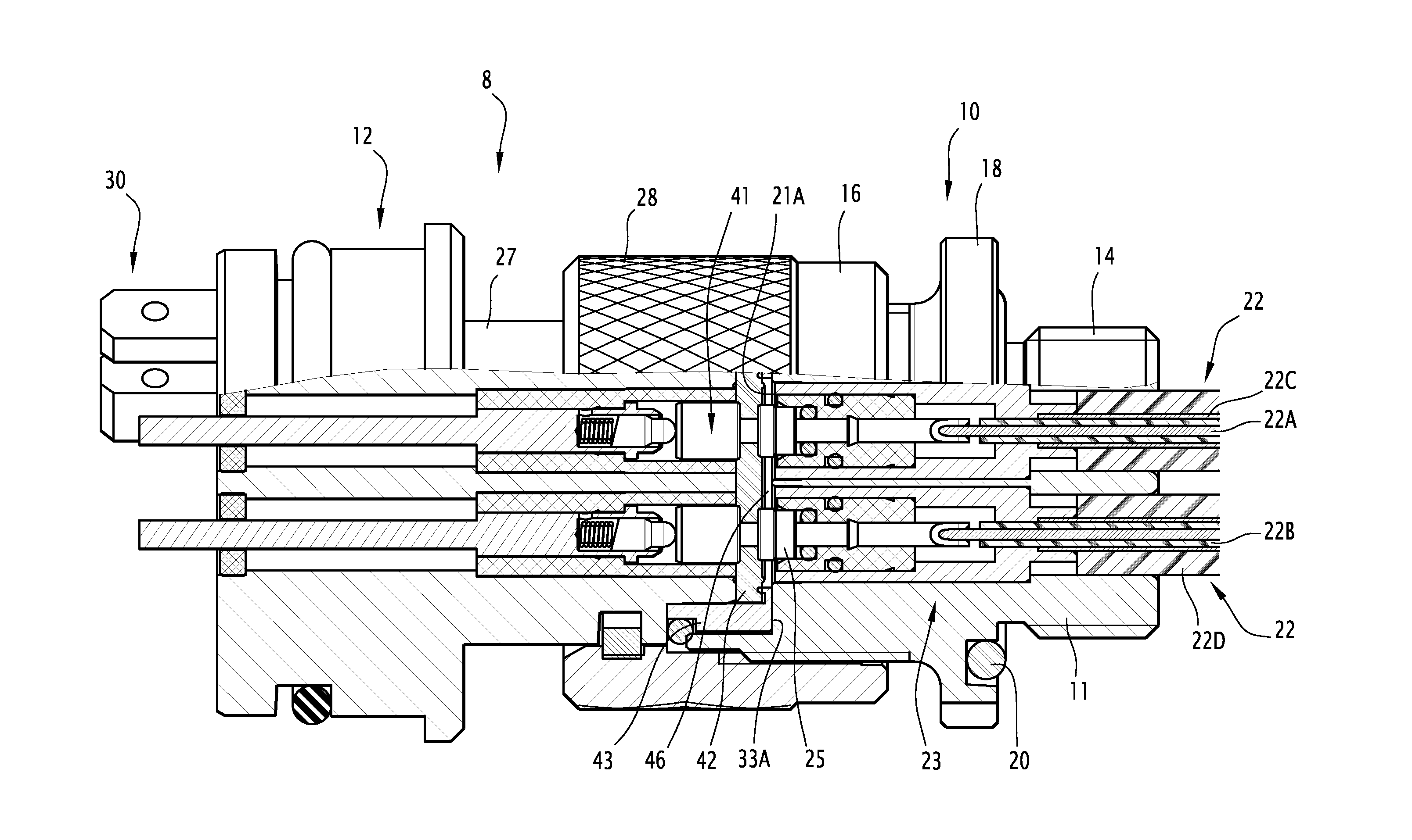
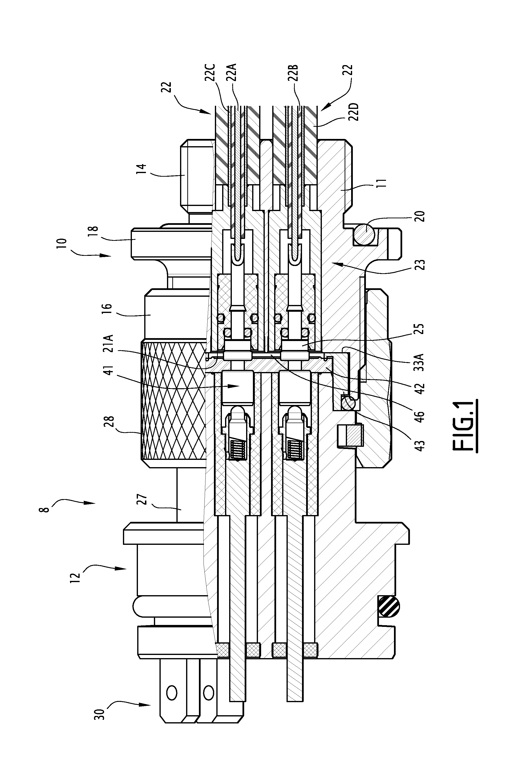
[0033]FIG. 1 shows an antenna interface 8 according to one example embodiment of the invention. Such an interface 8 is in particular designed to equip a radio receiver, for example a dual-band tactical radio receiver, to connect a dual-band antenna.

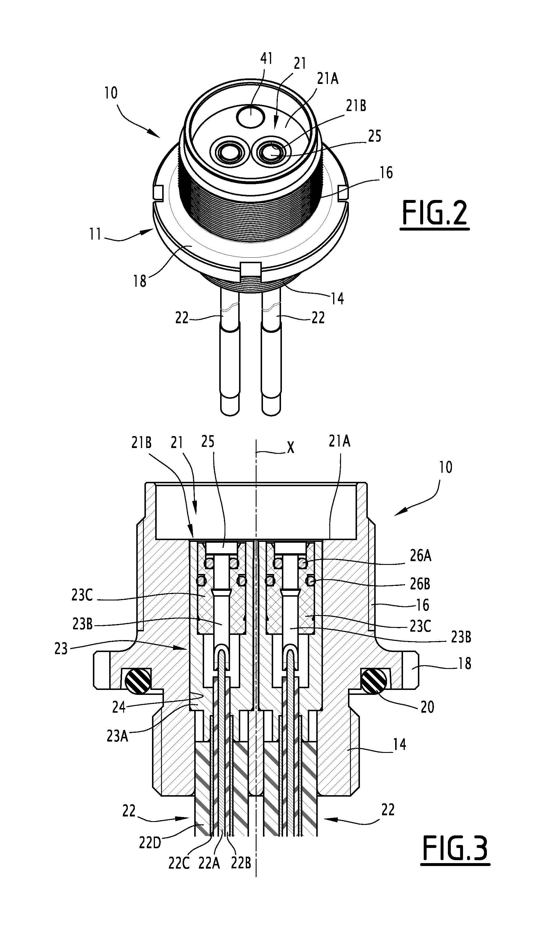
[0034]The interface 8 comprises a socket 10, in particular shown in FIGS. 2 to 4, and a plug 12, in particular shown in FIGS. 5 to 7, designed to cooperate with the socket 10 so as to form the interface 8 as shown in FIG. 1.

[0035]The socket 10 comprises a body 11, with a general shape of revolution around an axis X. This body 11 comprises a first portion 14 and a second portion 16, which are substantially cylindrical, and a flange 18 axially separating the first 14 and second 16 portions.

[0036]The first portion 14 has a threaded outer surface, designed to be screwed into a complementary opening of the radio receiver. The flange 18 then in particular forms an end-of-travel stop for said screwing.

[0037]It will be noted that the threaded out...


PUM


Abstract

The present invention provides an antenna interface. The antenna interface includes a socket and a plug. The socket includes a body and two coaxial cables, each having a core, a braid coaxial to the core, and an electric insulator between the core and the braid. Each coaxial cable extends between a first end connected to a printed circuit board of the receiver and a second end at which the braid is electrically connected to the body, and at which the core can be accessed through an opening made in the body. The plug includes a body and at least two contactors such that, when the plug and the socket are connected, each contactor is arranged opposite an opening such that the core of a respective cable is electrically connected to the contactor, and the braid of each cable is electrically connected to the body of the plug via the body.

Description

[0001]The present invention relates to an antenna interface for a radio receiver.BACKGROUND[0002]Already known in the state of the art is an antenna interface for a radio receiver, of the type comprising a socket, designed to be connected to the receiver, and a plug, designed to be connected to the antenna.[0003]Such interfaces are typically used for a single-band receiver, i.e. a receiver capable of transmitting and / or receiving on a single frequency band.[0004]In the case of a dual-band receiver, i.e. a receiver capable of transmitting and / or receiving on two distinct frequency bands, it is necessary to provide two distinct interface sockets. However, the use of two sockets is relatively bulky, which is in particular detrimental to miniaturization of the receiver.SUMMARY OF THE INVENTION[0005]An objection of the present invention may resolve this drawback, by allowing the connection of an antenna to a dual-band receiver, while limiting the bulk of the connection means.[0006]The pr...

Claims


Application Information

Patent Timeline
Patent Type & Authority Applications(United States)
IPC IPC(8): H01R9/05
CPCH01R13/2421H01R2201/02H01R24/52H01R13/6474H01R13/24
Inventor LE TORTOREC, CHRISTIANRETAILLEAU, XAVIERDEFFOIS, MATTHIEUBARBET, ANNEGRAMSAMER, JOSEF
Owner THALES SA
Why Eureka
Try Eureka